Biltong box
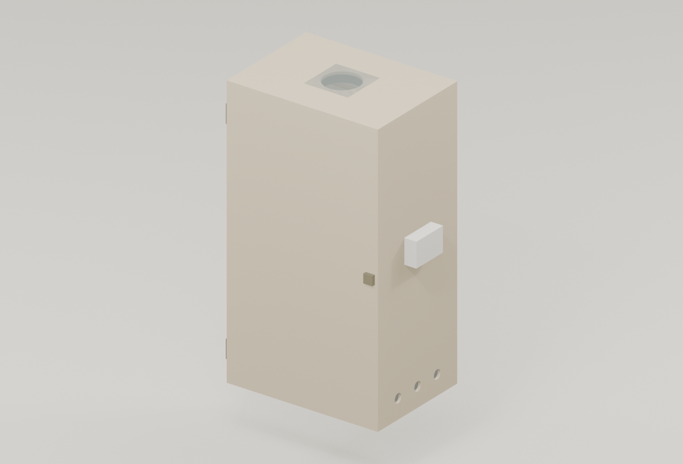
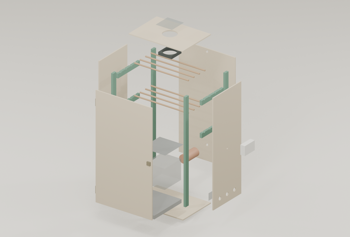
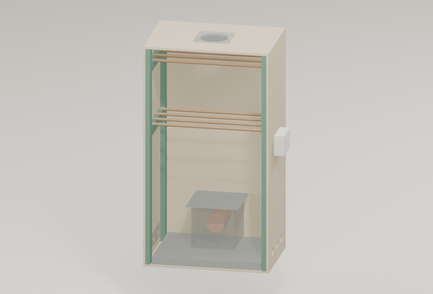
An upright plywood box with hanging dowels, a top fan, a guarded heat source and a drip tray, switched by a controller outside.
Default dimensions are shown below. Enable JavaScript to edit dimensions and inspect the 3D model.
Dimensions
- width
- 500 mm
- depth
- 350 mm
- height
- 900 mm
- sheet Thickness
- 9 mm
- cleat Section
- 19 mm, 38 mm
- dowel Diameter
- 12 mm
- board Length
- 2,400 mm
- dowel Stock Length
- 1,000 mm
- sheet
- 1,220 mm, 2,440 mm
- kerf
- 3 mm
- row Count
- 2
- dowels Per Row
- 4
- hook Spacing
- 40 mm
- top Clearance
- 60 mm
- drop
- 250 mm
- fan Size
- 120 mm
- inlet Diameter
- 30 mm
- inlet Count
- 3
- heat Source Count
- 1
- heat Source Diameter
- 70 mm
- heat Source Length
- 150 mm
- heat Source Clearance
- 50 mm
Shopping list
Quantities follow the dimensions above and have not been checked against a built example.
| Quantity | Item | Note |
|---|---|---|
| Timber | ||
| 4 1000 mm lengths | hardwood dowel12 mm × 12 mm section8 cuts · 136 mm offcut in total | First-fit estimate with the entered saw kerf. Check grain and defects before cutting. |
| 2 2400 mm lengths | softwood batten19 mm × 38 mm section8 cuts · 188 mm offcut in total | |
| Sheet | ||
| 1 sheet | 9 mm plywood | 1220 × 2440 mm sheets. Panels are placed one at a time with the entered kerf, not a full nesting plan. Check that the glue and faces suit food contact. |
| 1 piece to cut | sheet steel1 at 220 mm × 210 mmabout 0.05 m² of finished pieces, before overlaps and offcuts | The model gives finished sizes only; stock size and purchase quantity are not specified. |
| Mesh and screen | ||
| 1 piece | Heat guardsteel guard meshmodelled at 170 mm × 200 mm × 170 mm | Modelled geometry only; the material specification is not established. |
| 3 pieces to cut | insect mesh2 at 237 mm × 60 mm, 1 at 144 mm × 144 mmabout 0.05 m² of finished pieces, before overlaps and offcuts | The model gives finished sizes only; stock size and purchase quantity are not specified. |
| Fixings and hardware | ||
| 2 hinges | butt hinges | Size and screws to suit the door. |
| 1 latch | latch, magnetic or turn-button | Keeps the door shut; type to choose. |
| 88 hooks | S-hooks | 11 per dowel at 40 mm spacing. Material and wire size to choose. |
| 45 staples | staples | For the insect mesh, about 40 mm apart; size to suit the mesh. |
| 102 screws | wood screws | Countersunk, about 25 mm long, about 150 mm apart. Drill pilot holes; thin sheet edges split easily. |
| Bought parts | ||
| 3 grommets | cable grommets | One for the fan cable, one behind each heat source and one for the probe port. |
| 1 piece | Controller (space reserved)temperature and humidity controllermodelled at 40 mm × 120 mm × 80 mm | Bought part placed in the model. Choose the product and its rating; any wiring is for a competent person. |
| 1 piece | Drip traymetal or enamel traymodelled at 434 mm × 331 mm × 30 mm | |
| 1 piece | Fanextractor fanmodelled at 120 mm × 120 mm × 25 mm | |
| 1 piece | Heat sourceheat source in a lamp holdermodelled at 70 mm × 150 mm × 70 mm | |
| Sealants and coatings | ||
| glue, amount not specified | wood adhesive (PVA glue) | For the cleats and panel joints. |
Cutting plan
Stock allocation uses the model’s kerf rule and the default stock lengths. No piece is spliced to fit.
batten 1batten
2,400 mm- 882 mm
- 882 mm
- 265 mm
- 265 mm
Offcut 94 mm
batten 2batten
2,400 mm- 882 mm
- 882 mm
- 265 mm
- 265 mm
Offcut 94 mm
dowel 1dowel
1,000 mm- 480 mm
- 480 mm
Offcut 34 mm
dowel 2dowel
1,000 mm- 480 mm
- 480 mm
Offcut 34 mm
dowel 3dowel
1,000 mm- 480 mm
- 480 mm
Offcut 34 mm
dowel 4dowel
1,000 mm- 480 mm
- 480 mm
Offcut 34 mm
plywood 1
1,220 mm × 2,440 mm- 500 mm × 900 mm
- 500 mm × 900 mm
- 341 mm × 900 mm
- 900 mm × 341 mm· turned
- 341 mm × 482 mm
- 341 mm × 482 mm
Placed one piece at a time with the entered kerf; not a nesting plan.
Cut list
| Part | Stock | Cut | Joint and angles |
|---|---|---|---|
| plywood | 900 mm × 341 mm | Cut and joint details require physical verification. Saw angle from square 0° | |
| plywood | 900 mm × 341 mm | Cut and joint details require physical verification. Saw angle from square 0° | |
| plywood | 900 mm × 500 mm | Cut and joint details require physical verification. Saw angle from square 0° | |
| plywood | 482 mm × 341 mm | Cut and joint details require physical verification. Saw angle from square 0° | |
| plywood | 482 mm × 341 mm | Cut and joint details require physical verification. Saw angle from square 0° | |
| plywood | 900 mm × 500 mm | Cut and joint details require physical verification. Saw angle from square 0° | |
| batten | 882 mm × 38 mm | Cut and joint details require physical verification. Saw angle from square 0° | |
| batten | 882 mm × 38 mm | Cut and joint details require physical verification. Saw angle from square 0° | |
| batten | 882 mm × 38 mm | Cut and joint details require physical verification. Saw angle from square 0° | |
| batten | 882 mm × 38 mm | Cut and joint details require physical verification. Saw angle from square 0° | |
| batten | 265 mm × 38 mm | Cut and joint details require physical verification. Saw angle from square 0° | |
| batten | 265 mm × 38 mm | Cut and joint details require physical verification. Saw angle from square 0° | |
| dowel | 480 mm × 12 mm | Cut and joint details require physical verification. Saw angle from square 0° | |
| dowel | 480 mm × 12 mm | Cut and joint details require physical verification. Saw angle from square 0° | |
| dowel | 480 mm × 12 mm | Cut and joint details require physical verification. Saw angle from square 0° | |
| dowel | 480 mm × 12 mm | Cut and joint details require physical verification. Saw angle from square 0° | |
| batten | 265 mm × 38 mm | Cut and joint details require physical verification. Saw angle from square 0° | |
| batten | 265 mm × 38 mm | Cut and joint details require physical verification. Saw angle from square 0° | |
| dowel | 480 mm × 12 mm | Cut and joint details require physical verification. Saw angle from square 0° | |
| dowel | 480 mm × 12 mm | Cut and joint details require physical verification. Saw angle from square 0° | |
| dowel | 480 mm × 12 mm | Cut and joint details require physical verification. Saw angle from square 0° | |
| dowel | 480 mm × 12 mm | Cut and joint details require physical verification. Saw angle from square 0° | |
| guard mesh | 570 mm × 570 mm | Cut and joint details require physical verification. Saw angle from square 0° | |
| steel sheet | 220 mm × 210 mm | Cut and joint details require physical verification. Saw angle from square 0° | |
| insect mesh | 237 mm × 60 mm | Cut and joint details require physical verification. Saw angle from square 0° | |
| insect mesh | 237 mm × 60 mm | Cut and joint details require physical verification. Saw angle from square 0° | |
| insect mesh | 144 mm × 144 mm | Cut and joint details require physical verification. Saw angle from square 0° |
Openings and fitted details
- id
- cable.heat.1
- type
- circle
- diameter
- 20 mm
- centre
- 250 mm, 346 mm, 129 mm
- target Id
- panel.back
- axis
- y
- status
- cable hole behind the holder base
- id
- inlet.left.1
- type
- circle
- diameter
- 30 mm
- centre
- 5 mm, 82 mm, 64 mm
- target Id
- panel.left
- axis
- x
- status
- proposal
- id
- inlet.left.2
- type
- circle
- diameter
- 30 mm
- centre
- 5 mm, 171 mm, 64 mm
- target Id
- panel.left
- axis
- x
- status
- proposal
- id
- inlet.left.3
- type
- circle
- diameter
- 30 mm
- centre
- 5 mm, 259 mm, 64 mm
- target Id
- panel.left
- axis
- x
- status
- proposal
- id
- inlet.right.1
- type
- circle
- diameter
- 30 mm
- centre
- 496 mm, 82 mm, 64 mm
- target Id
- panel.right
- axis
- x
- status
- proposal
- id
- inlet.right.2
- type
- circle
- diameter
- 30 mm
- centre
- 496 mm, 171 mm, 64 mm
- target Id
- panel.right
- axis
- x
- status
- proposal
- id
- inlet.right.3
- type
- circle
- diameter
- 30 mm
- centre
- 496 mm, 259 mm, 64 mm
- target Id
- panel.right
- axis
- x
- status
- proposal
- id
- outlet.top
- type
- circle
- diameter
- 114 mm
- centre
- 250 mm, 171 mm, 896 mm
- target Id
- panel.top
- axis
- z
- status
- proposal; check against the fan blade circle
- id
- cable.fan
- type
- circle
- diameter
- 20 mm
- centre
- 250 mm, 346 mm, 876 mm
- target Id
- panel.back
- axis
- y
- status
- fan cable leaves through the back
- id
- probe.port
- type
- circle
- diameter
- 16 mm
- centre
- 496 mm, 171 mm, 432 mm
- target Id
- panel.right
- axis
- x
- status
- probe port beside the controller; grommet to suit the probe cable
Parts
| Part | Material | Size | Basis |
|---|---|---|---|
| plywood | 9 mm × 341 mm × 900 mm | proposal | |
| plywood | 9 mm × 341 mm × 900 mm | proposal | |
| plywood | 500 mm × 9 mm × 900 mm | proposal | |
| plywood | 482 mm × 341 mm × 9 mm | proposal | |
| plywood | 482 mm × 341 mm × 9 mm | proposal | |
| plywood | 500 mm × 9 mm × 900 mm | proposal | |
| softwood batten | 19 mm × 38 mm × 882 mm | proposal | |
| softwood batten | 19 mm × 38 mm × 882 mm | proposal | |
| softwood batten | 19 mm × 38 mm × 882 mm | proposal | |
| softwood batten | 19 mm × 38 mm × 882 mm | proposal | |
| softwood batten | 19 mm × 265 mm × 38 mm | proposal | |
| softwood batten | 19 mm × 265 mm × 38 mm | proposal | |
| hardwood dowel | 480 mm × 12 mm × 12 mm | proposal | |
| hardwood dowel | 480 mm × 12 mm × 12 mm | proposal | |
| hardwood dowel | 480 mm × 12 mm × 12 mm | proposal | |
| hardwood dowel | 480 mm × 12 mm × 12 mm | proposal | |
| softwood batten | 19 mm × 265 mm × 38 mm | proposal | |
| softwood batten | 19 mm × 265 mm × 38 mm | proposal | |
| hardwood dowel | 480 mm × 12 mm × 12 mm | proposal | |
| hardwood dowel | 480 mm × 12 mm × 12 mm | proposal | |
| hardwood dowel | 480 mm × 12 mm × 12 mm | proposal | |
| hardwood dowel | 480 mm × 12 mm × 12 mm | proposal | |
| metal or enamel tray | 434 mm × 331 mm × 30 mm | largest tray that slides out between the cleats; buy one this size or smaller | |
| steel guard mesh | 170 mm × 200 mm × 170 mm | clearance envelope; guard type to suit the heat source | |
| sheet steel | 210 mm × 220 mm × 1 mm | proposal; keeps drips off the heat source | |
| heat source in a lamp holder | 70 mm × 150 mm × 70 mm | envelope of holder and bulb or emitter; enter your own | |
| insect mesh | 1 mm × 237 mm × 60 mm | proposal | |
| insect mesh | 1 mm × 237 mm × 60 mm | proposal | |
| extractor fan | 120 mm × 120 mm × 25 mm | bought component; frame size entered, depth proposed | |
| insect mesh | 144 mm × 144 mm × 1 mm | proposal | |
| temperature and humidity controller | 40 mm × 120 mm × 80 mm | generic space reserved on the outside; not the size of any particular device | |
| hinge | 3 mm × 30 mm × 60 mm | position marker; hinge size not selected | |
| hinge | 3 mm × 30 mm × 60 mm | position marker; hinge size not selected | |
| door latch | 30 mm × 12 mm × 30 mm | position marker; magnetic or turn button latch |
Build steps and tools
Choose the bought parts first
Buy the fan, the heat source and its holder, and the controller before you cut anything, then enter their sizes and the clearances the heat source maker states. Plain incandescent bulbs are no longer sold for household lighting in the UK and EU. Builders now use a ceramic heat emitter, which gives heat and no light, in the porcelain holder its maker specifies; an infrared heat lamp; or a small oven lamp. The UK rules exempt lamps made for ovens (up to 40 W) and for infrared heating (100 to 400 W). A box can also run on the fan alone: set the heat sources to 0.
Tape measure. A tubular or greenhouse heater also works but needs its own position and guard low on the back; this model does not draw one.
tape measureCut the panels
Mark the sides, back, top, floor and door from the cutting plan and cut them square. Sand the edges that face the food space.
Circular saw with a guide, jigsaw or handsaw, with a square and pencil. A mitre saw cannot cut sheet.
circular sawjigsawhandsawsquaremarking pencilCut the cleats, rails and dowels
Crosscut the four corner cleats, two rails for each row and the dowels to the listed lengths. Clamp the two rails of a row together top edge to top edge, mark the notch centres on the joint and drill each notch with a bit 1 mm larger than the dowel. Each rail gets a half-round seat, and the dowels lift out for cleaning.
Handsaw or mitre saw for the crosscuts; clamps, drill/driver and a sharp bit for the notches.
handsawmitre sawclampdrill driverdrill bitDrill the openings
Drill the inlet holes low in both sides, the probe port in the right side and the cable holes in the back. Cut the fan opening in the top.
Drill/driver with a hole saw for the round holes; a jigsaw for a fan opening larger than your hole saws.
drill driverhole sawjigsawAssemble the box
Glue and screw the cleats into the corners, then fit the floor and the top between the sides and screw on the back. Drill a pilot and countersink for every screw; thin sheet edges split easily. Screw the rails to the sides at the marked heights and check that every dowel lifts in and out. Hang the door and fit the latch.
Drill/driver with pilot, countersink and driver bits; clamps and a square to hold the corners true.
drill driverdrill bitcountersink bitdriver bitclampsquareFit the screens and the tray
Staple insect mesh over the inlets on the inside and over the outlet on the top. Slide in a drip tray no larger than the listed size.
Staple gun; scissors-type shears or a knife for the mesh.
staple gunshearsutility knifePlace the fan, heat source and controller
Fix the fan under the outlet so it blows out. Fix the heat source holders to the back above the tray, with the guard around them and the drip shield over the guard, so drips land on the shield and not on a hot bulb or emitter. Mount the controller outside the right side and pass its probe through the probe port into the hanging space. The controller switches the heat source to hold the temperature and runs the fan when humidity rises. A competent person chooses the cables and does all the mains wiring; a 12 V PC fan also needs its own low-voltage supply.
Screwdriver or drill/driver. The cable routes are in the openings list.
screwdriverdrill driverCheck before use
Run the box empty with the door shut. Check that the controller switches the heat source and the fan, and feel how warm the guard, the shield and the wood near them get. This model sets no temperature, humidity or drying time.
A temperature and humidity instrument to compare with the controller reading.
hygrometer
Tools by operation
measure and mark
Measure the sheet, cleats, dowels and the bought fan and heat source, then mark the panels from the cutting plan
cut panels
Cut the sides, back, top, floor and door from sheet
cut cleats and dowels
Crosscut the corner cleats, the hanging rails and the dowels
notch rails
Clamp each pair of rails top edge to top edge and drill the dowel notches on the joint line
drill openings
Drill the inlet holes, probe port and cable holes, and cut the fan opening in the top
assemble box
Glue and screw cleats, panels and rails with pilot holes; hang the door and fit the latch
fit screens
Cut insect mesh and staple it over the inlets and the outlet
place components
Place the fan, heat source holders, guard, drip shield and controller in their marked positions; a competent person wires them
check before use
Run the box empty and check that the controller switches the fan and the heat source, and how warm the guard, shield and nearby wood get
Before you build
A competent person needs to check the airflow, the heat source and its clearances, the controller and all wiring before use. Hanging loads, joints, food-contact surfaces and the drying process itself are untested.
- A competent person needs to check the airflow, the heat source and its clearances, the controller and all wiring before use. Hanging loads, joints, food-contact surfaces and the drying process itself are untested.
- Panels, cleats, rails, dowels and holes follow the model; in this view the rail notches are listed but not cut. The fan, heat sources, guard, drip shield, tray and controller are envelopes of bought parts, and the hinges and latch are position markers. Insect mesh is a translucent sheet. Cables are not drawn; their routes are in the openings list.
- Every dimension is a proposal for an original design. Measure your sheet, cleats, fan and heat source and enter the real sizes.
What the 3D model leaves out
Panels, cleats, rails, dowels and holes follow the model; in this view the rail notches are listed but not cut. The fan, heat sources, guard, drip shield, tray and controller are envelopes of bought parts, and the hinges and latch are position markers. Insect mesh is a translucent sheet. Cables are not drawn; their routes are in the openings list.
Taking the model apart separates parts for inspection; it is not an assembly order.
Dimension evidence and geometric checks
- layout
- An upright box, taller than wide, with air entering low and leaving above the meat: aCuriousCreator, Wooden Biltong Box, Instructables, 2017.
- dowels
- Two levels of dowels in an 18 × 18 × 24 in plywood box on 1 × 1 in cleats, with drilled-and-split dowel holders: burtj459, Biltong Dryer, Instructables, 2020. The model notches the rails the same way.
- heat
- A 40 W bulb in a mains lamp kit (aCuriousCreator, 2017) and a bulb holder low in a corner (burtj459, 2020). The model reserves a guarded position for up to four screw-in heat sources and gives no wattage.
- fan
- A PC fan in each build: one blows in low (aCuriousCreator, 2017), two blow out (burtj459, 2020; Dhunter1469, Biltong Maker, Instructables, 2011). This model extracts at the top.
- controller
- The heat source and the fan are switched separately by a controller outside the box: the heat holds the temperature and the fan runs when humidity rises. This follows the project owner’s working box; the model sets no temperature or humidity.
- id
- positive-dimensions
- ok
- Yes
- id
- dowels-seated
- ok
- Yes
- detail
- Each dowel rests at the bottom of its rail notch.
- id
- fan-above-dowels
- ok
- Yes
- detail
- The top dowels sit below the fan.
- id
- hanging-clear-of-heat
- ok
- Yes
- clearance
- 42 mm
- detail
- Geometric clearance only; the clearances the heat source maker states still apply.
- id
- stock-fit
- ok
- Yes
- id
- tray-removable
- ok
- Yes
- detail
- The tray clears the cleats and slides out under the guard.
Reference renders
Fixed views of the original proposal. They do not change with your dimensions.