Cold-smoking cabinet
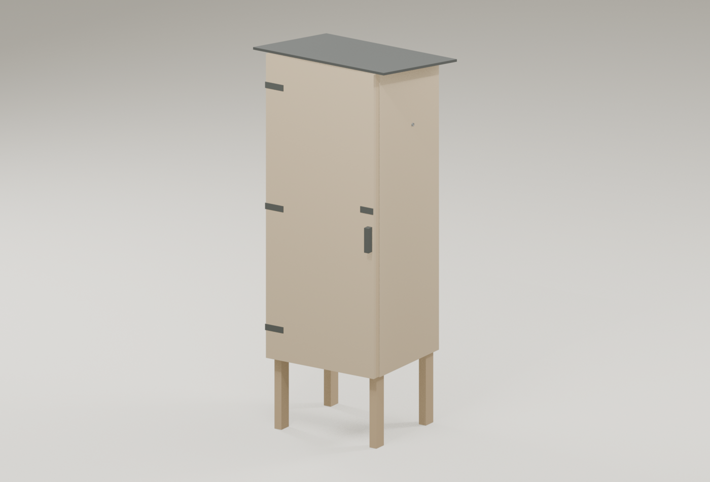
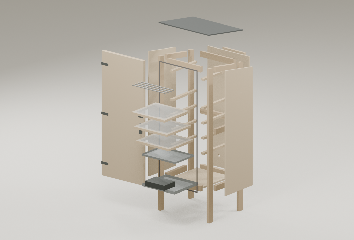
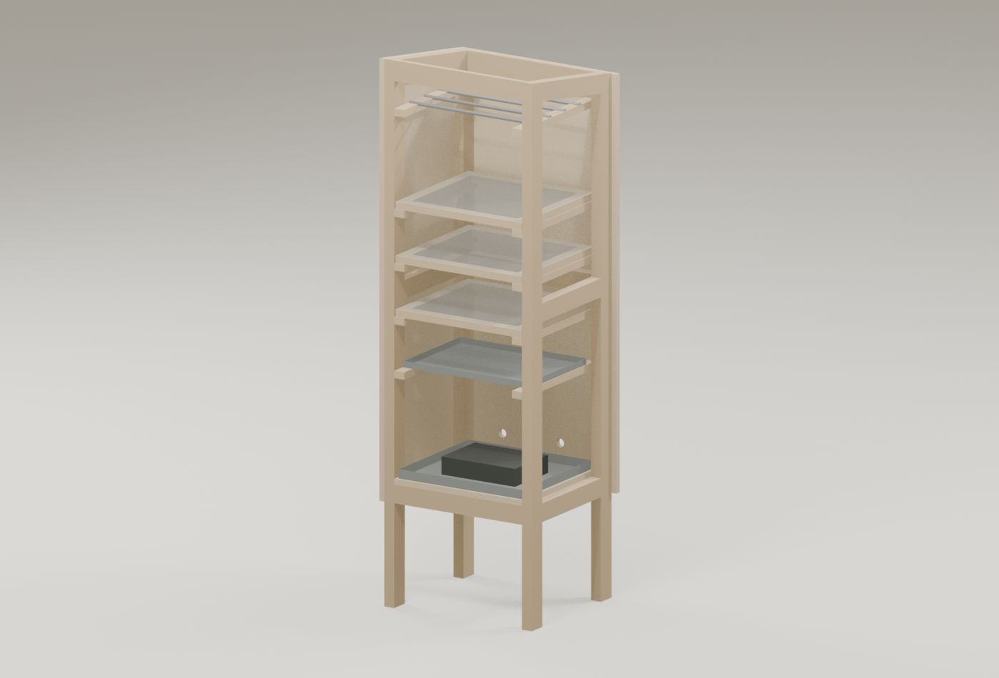
A tall timber cabinet on legs around a bought maze smoke generator, with hanging rods, mesh shelves, a drip tray and sliding vents.
Default dimensions are shown below. Enable JavaScript to edit dimensions and inspect the 3D model.
Dimensions
- width
- 600 mm
- depth
- 500 mm
- height
- 1,400 mm
- leg Height
- 350 mm
- roof Rise
- 80 mm
- roof Overhang
- 60 mm
- frame Section
- 38 mm, 63 mm
- batten Section
- 25 mm, 38 mm
- board Thickness
- 19 mm
- board Width
- 125 mm
- board Coverage
- 110 mm
- roof Thickness
- 12 mm
- frame Stock Length
- 2,400 mm
- board Stock Length
- 2,400 mm
- roof Sheet
- 1,220 mm, 2,440 mm
- kerf
- 3 mm
- rod Count
- 4
- rod Diameter
- 12 mm
- shelf Count
- 3
- shelf Spacing
- 180 mm
- door Gap
- 3 mm
- vent Diameter
- 30 mm
- generator Width
- 280 mm
- generator Depth
- 200 mm
- generator Height
- 60 mm
- generator Clearance
- 300 mm
Shopping list
Quantities follow the dimensions above and have not been checked against a built example.
| Quantity | Item | Note |
|---|---|---|
| Timber | ||
| 6 2400 mm lengths | planed softwood38 mm × 63 mm section15 cuts · 2,580 mm offcut in total | First-fit estimate with the entered saw kerf. Check grain and defects before cutting. |
| 7 2400 mm lengths | softwood batten25 mm × 38 mm section31 cuts · 1,469 mm offcut in total | |
| 22 2400 mm lengths | tongue-and-groove softwood19 mm × 110 mm section · 19 mm × 125 mm boards, 110 mm cover27 cuts · 18,622 mm offcut in total | |
| Metal lengths | ||
| 4 rods | stainless steel rod12 mm diameter, 480 mm long | |
| Sheet | ||
| 1 sheet | exterior plywood1,220 mm × 2,440 mm sheet1 panel placed with the entered kerf | Individual placement, not a full nesting plan. |
| 1 piece | galvanised steel, base-tray blank526 mm × 483 mm | |
| 1 piece | galvanised steel, drip-tray blank520 mm × 383 mm | |
| 0.45 m² | roofing felt | Roof board area without laps or turn-downs. |
| 2 pieces | vent slide plate, stainless steel280 mm × 60 mm | |
| Mesh and screen | ||
| 3 pieces | stainless steel mesh470 mm × 427 mm | |
| Fixings and hardware | ||
| 1 handle | door handle | |
| 3 hinges | door hinges | Type and size to suit an overlay door. |
| 4 m | door seal strip | Centreline of the seal loop, 12 × 4 mm section. Heat and food-contact rating not checked. |
| 1 set | hasp or turn button | Holds the door against the seal. |
| 44 screws | screws, 100 mm | 44 for rail ends, two each. Gauge and coating to suit the timber. |
| 172 screws | screws, 45 mm | 152 for boards, two per rail crossed; 20 for the roof board at 150 mm spacing. Gauge and coating to suit the timber. |
| 88 screws | screws, 70 mm | 88 for battens, door and shelf frames and vent guides. Gauge and coating to suit the timber. |
| 108 staples | staples for mesh | At 50 mm spacing around each shelf. |
| Bought parts | ||
| 1 generator | maze cold-smoke generator | Bought ready-made. The model reserves the footprint and height you entered. |
| 1 piece | probe sleeve or grommet | For a 16 mm hole through a 19 mm board. |
| Sealants and coatings | ||
| coating, amount not specified | wood finish for outside faces | Product and amount not chosen. This design leaves the inside bare. |
Cutting plan
Stock allocation uses the model’s kerf rule and the default stock lengths. No piece is spliced to fit.
frame 1frame
2,400 mm- 1,830 mm
- 486 mm
Offcut 78 mm
frame 2frame
2,400 mm- 1,830 mm
- 486 mm
Offcut 78 mm
frame 3frame
2,400 mm- 1,763 mm
- 486 mm
Offcut 145 mm
frame 4frame
2,400 mm- 1,763 mm
- 486 mm
Offcut 145 mm
frame 5frame
2,400 mm- 486 mm
- 370 mm
- 370 mm
- 355 mm
- 355 mm
- 355 mm
Offcut 92 mm
frame 6frame
2,400 mm- 355 mm
Offcut 2,042 mm
batten 1batten
2,400 mm- 1,474 mm
- 518 mm
- 315 mm
Offcut 84 mm
batten 2batten
2,400 mm- 1,474 mm
- 518 mm
- 315 mm
Offcut 84 mm
batten 3batten
2,400 mm- 518 mm
- 443 mm
- 443 mm
- 443 mm
- 443 mm
Offcut 95 mm
batten 4batten
2,400 mm- 443 mm
- 443 mm
- 443 mm
- 443 mm
- 443 mm
Offcut 170 mm
batten 5batten
2,400 mm- 443 mm
- 437 mm
- 437 mm
- 437 mm
- 437 mm
Offcut 194 mm
batten 6batten
2,400 mm- 437 mm
- 437 mm
- 404 mm
- 404 mm
- 404 mm
Offcut 299 mm
batten 7batten
2,400 mm- 404 mm
- 404 mm
- 404 mm
- 315 mm
- 315 mm
Offcut 543 mm
board 1board
2,400 mm- 1,480 mm
- 481 mm
Offcut 433 mm
board 2board
2,400 mm- 1,480 mm
- 481 mm
Offcut 433 mm
board 3board
2,400 mm- 1,474 mm
- 481 mm
Offcut 439 mm
board 4board
2,400 mm- 1,474 mm
- 481 mm
Offcut 439 mm
board 5board
2,400 mm- 1,474 mm
- 481 mm
Offcut 439 mm
board 6board
2,400 mm- 1,474 mm
Offcut 923 mm
board 7board
2,400 mm- 1,474 mm
Offcut 923 mm
board 8board
2,400 mm- 1,474 mm
Offcut 923 mm
board 9board
2,400 mm- 1,462 mm
Offcut 935 mm
board 10board
2,400 mm- 1,462 mm
Offcut 935 mm
board 11board
2,400 mm- 1,445 mm
Offcut 952 mm
board 12board
2,400 mm- 1,445 mm
Offcut 952 mm
board 13board
2,400 mm- 1,427 mm
Offcut 970 mm
board 14board
2,400 mm- 1,427 mm
Offcut 970 mm
board 15board
2,400 mm- 1,410 mm
Offcut 987 mm
board 16board
2,400 mm- 1,410 mm
Offcut 987 mm
board 17board
2,400 mm- 1,400 mm
Offcut 997 mm
board 18board
2,400 mm- 1,400 mm
Offcut 997 mm
board 19board
2,400 mm- 1,400 mm
Offcut 997 mm
board 20board
2,400 mm- 1,400 mm
Offcut 997 mm
board 21board
2,400 mm- 1,400 mm
Offcut 997 mm
board 22board
2,400 mm- 1,400 mm
Offcut 997 mm
roof ply 1
1,220 mm × 2,440 mm- 720 mm × 628 mm
Placed one piece at a time with the entered kerf; not a nesting plan.
Cut list
| Part | Stock | Cut | Joint and angles |
|---|---|---|---|
| frame | 1,830 mm × 63 mm | top cut to the 9.09° roof pitch; rails screwed between the posts Ends 90° / 80.91° | |
| frame | 1,763 mm × 63 mm | top cut to the 9.09° roof pitch; rails screwed between the posts Ends 90° / 80.91° | |
| frame | 1,830 mm × 63 mm | top cut to the 9.09° roof pitch; rails screwed between the posts Ends 90° / 80.91° | |
| frame | 1,763 mm × 63 mm | top cut to the 9.09° roof pitch; rails screwed between the posts Ends 90° / 80.91° | |
| frame | 355 mm × 63 mm | square ends; screw fixing Ends 90° / 90° | |
| frame | 355 mm × 63 mm | square ends; screw fixing Ends 90° / 90° | |
| frame | 370 mm × 63 mm | both ends plumb-cut at 9.09° from square; lies under the roof board Ends 80.91° / 80.91° | |
| frame | 355 mm × 63 mm | square ends; screw fixing Ends 90° / 90° | |
| frame | 355 mm × 63 mm | square ends; screw fixing Ends 90° / 90° | |
| frame | 370 mm × 63 mm | both ends plumb-cut at 9.09° from square; lies under the roof board Ends 80.91° / 80.91° | |
| frame | 486 mm × 63 mm | square ends; screw fixing Ends 90° / 90° | |
| frame | 486 mm × 63 mm | square ends; screw fixing Ends 90° / 90° | |
| frame | 486 mm × 63 mm | square ends; screw fixing Ends 90° / 90° | |
| frame | 486 mm × 63 mm | top edge bevelled to the 9.09° roof pitch Ends 90° / 90° | |
| frame | 486 mm × 63 mm | top edge bevelled to the 9.09° roof pitch Ends 90° / 90° | |
| board | 481 mm × 125 mm | full board Ends 90° / 90° | |
| board | 481 mm × 125 mm | full board Ends 90° / 90° | |
| board | 481 mm × 125 mm | full board Ends 90° / 90° | |
| board | 481 mm × 125 mm | full board Ends 90° / 90° | |
| board | 481 mm × 46 mm | rip to 46 mm exposed width; keep the tongue edge Ends 90° / 90° | |
| board | 1,480 mm × 125 mm | top cut to the 9.09° roof pitch Ends 90° / 80.91° | |
| board | 1,462 mm × 125 mm | top cut to the 9.09° roof pitch Ends 90° / 80.91° | |
| board | 1,445 mm × 125 mm | top cut to the 9.09° roof pitch Ends 90° / 80.91° | |
| board | 1,427 mm × 125 mm | top cut to the 9.09° roof pitch Ends 90° / 80.91° | |
| board | 1,410 mm × 41 mm | top cut to the 9.09° roof pitch; rip to 41 mm exposed width Ends 90° / 80.91° | |
| board | 1,480 mm × 125 mm | top cut to the 9.09° roof pitch Ends 90° / 80.91° | |
| board | 1,462 mm × 125 mm | top cut to the 9.09° roof pitch Ends 90° / 80.91° | |
| board | 1,445 mm × 125 mm | top cut to the 9.09° roof pitch Ends 90° / 80.91° | |
| board | 1,427 mm × 125 mm | top cut to the 9.09° roof pitch Ends 90° / 80.91° | |
| board | 1,410 mm × 41 mm | top cut to the 9.09° roof pitch; rip to 41 mm exposed width Ends 90° / 80.91° | |
| board | 1,400 mm × 125 mm | full board Ends 90° / 90° | |
| board | 1,400 mm × 125 mm | full board Ends 90° / 90° | |
| board | 1,400 mm × 125 mm | full board Ends 90° / 90° | |
| board | 1,400 mm × 125 mm | full board Ends 90° / 90° | |
| board | 1,400 mm × 125 mm | full board Ends 90° / 90° | |
| board | 1,400 mm × 50 mm | rip to 50 mm exposed width; keep the tongue edge Ends 90° / 90° | |
| roof ply | 628 mm × 720 mm | square-cut board; screw to the posts and top rails; cover with roofing felt Ends 90° / 90° | |
| batten | 1,474 mm × 38 mm | square ends; screw fixing Ends 90° / 90° | |
| batten | 1,474 mm × 38 mm | square ends; screw fixing Ends 90° / 90° | |
| batten | 518 mm × 38 mm | butt between the stiles; two screws through each stile Ends 90° / 90° | |
| batten | 518 mm × 38 mm | butt between the stiles; two screws through each stile Ends 90° / 90° | |
| batten | 518 mm × 38 mm | butt between the stiles; two screws through each stile Ends 90° / 90° | |
| board | 1,474 mm × 125 mm | full board Ends 90° / 90° | |
| board | 1,474 mm × 125 mm | full board Ends 90° / 90° | |
| board | 1,474 mm × 125 mm | full board Ends 90° / 90° | |
| board | 1,474 mm × 125 mm | full board Ends 90° / 90° | |
| board | 1,474 mm × 125 mm | full board Ends 90° / 90° | |
| board | 1,474 mm × 44 mm | rip to 44 mm exposed width; keep the tongue edge Ends 90° / 90° | |
| tray blank | 526 mm × 483 mm | blank with 30 mm edges folded up; corners notched or folded Ends 90° / 90° | |
| batten | 443 mm × 38 mm | screwed to the front and back post faces Ends 90° / 90° | |
| batten | 443 mm × 38 mm | screwed to the front and back post faces Ends 90° / 90° | |
| tray blank | 520 mm × 383 mm | blank with 20 mm edges folded up; corners notched or folded Ends 90° / 90° | |
| batten | 443 mm × 38 mm | screwed to the front and back post faces Ends 90° / 90° | |
| batten | 443 mm × 38 mm | screwed to the front and back post faces Ends 90° / 90° | |
| batten | 437 mm × 38 mm | square ends; screw fixing Ends 90° / 90° | |
| batten | 437 mm × 38 mm | square ends; screw fixing Ends 90° / 90° | |
| batten | 404 mm × 38 mm | butt between the frame sides; two screws each end Ends 90° / 90° | |
| batten | 404 mm × 38 mm | butt between the frame sides; two screws each end Ends 90° / 90° | |
| mesh | 470 mm × 427 mm | stapled to the frame top at 50 mm spacing; turn cut wire ends down Ends 90° / 90° | |
| batten | 443 mm × 38 mm | screwed to the front and back post faces Ends 90° / 90° | |
| batten | 443 mm × 38 mm | screwed to the front and back post faces Ends 90° / 90° | |
| batten | 437 mm × 38 mm | square ends; screw fixing Ends 90° / 90° | |
| batten | 437 mm × 38 mm | square ends; screw fixing Ends 90° / 90° | |
| batten | 404 mm × 38 mm | butt between the frame sides; two screws each end Ends 90° / 90° | |
| batten | 404 mm × 38 mm | butt between the frame sides; two screws each end Ends 90° / 90° | |
| mesh | 470 mm × 427 mm | stapled to the frame top at 50 mm spacing; turn cut wire ends down Ends 90° / 90° | |
| batten | 443 mm × 38 mm | screwed to the front and back post faces Ends 90° / 90° | |
| batten | 443 mm × 38 mm | screwed to the front and back post faces Ends 90° / 90° | |
| batten | 437 mm × 38 mm | square ends; screw fixing Ends 90° / 90° | |
| batten | 437 mm × 38 mm | square ends; screw fixing Ends 90° / 90° | |
| batten | 404 mm × 38 mm | butt between the frame sides; two screws each end Ends 90° / 90° | |
| batten | 404 mm × 38 mm | butt between the frame sides; two screws each end Ends 90° / 90° | |
| mesh | 470 mm × 427 mm | stapled to the frame top at 50 mm spacing; turn cut wire ends down Ends 90° / 90° | |
| batten | 443 mm × 38 mm | screwed to the post faces; 4 notches 14 mm wide and 6 mm deep at 89, 177, 266, 354 mm from the front Ends 90° / 90° | |
| batten | 443 mm × 38 mm | screwed to the post faces; 4 notches 14 mm wide and 6 mm deep at 89, 177, 266, 354 mm from the front Ends 90° / 90° | |
| rod | 480 mm × 12 mm | cut square and deburr the ends Ends 90° / 90° | |
| rod | 480 mm × 12 mm | cut square and deburr the ends Ends 90° / 90° | |
| rod | 480 mm × 12 mm | cut square and deburr the ends Ends 90° / 90° | |
| rod | 480 mm × 12 mm | cut square and deburr the ends Ends 90° / 90° | |
| plate | 280 mm × 60 mm | 3 holes of 30 mm matching the wall; slides 35 mm to close Ends 90° / 90° | |
| batten | 315 mm × 38 mm | rebate 2 mm × 12 mm along the plate edge so the plate slides under it Ends 90° / 90° | |
| batten | 315 mm × 38 mm | rebate 2 mm × 12 mm along the plate edge so the plate slides under it Ends 90° / 90° | |
| plate | 280 mm × 60 mm | 3 holes of 30 mm matching the wall; slides 35 mm to close Ends 90° / 90° | |
| batten | 315 mm × 38 mm | rebate 2 mm × 12 mm along the plate edge so the plate slides under it Ends 90° / 90° | |
| batten | 315 mm × 38 mm | rebate 2 mm × 12 mm along the plate edge so the plate slides under it Ends 90° / 90° |
Openings and fitted details
- holes
- id
- vent.top.hole.wall.back.board.02
- target id
- wall.back.board.02
- axis
- y
- centre
- 165 mm, 491 mm, 1,670 mm
- diameter
- 30 mm
- depth
- 19 mm
- id
- vent.top.plate-hole.wall.back.board.02
- target id
- vent.top.plate
- axis
- y
- centre
- 165 mm, 501 mm, 1,670 mm
- diameter
- 30 mm
- depth
- 1 mm
- id
- vent.top.hole.wall.back.board.03
- target id
- wall.back.board.03
- axis
- y
- centre
- 275 mm, 491 mm, 1,670 mm
- diameter
- 30 mm
- depth
- 19 mm
- id
- vent.top.plate-hole.wall.back.board.03
- target id
- vent.top.plate
- axis
- y
- centre
- 275 mm, 501 mm, 1,670 mm
- diameter
- 30 mm
- depth
- 1 mm
- id
- vent.top.hole.wall.back.board.04
- target id
- wall.back.board.04
- axis
- y
- centre
- 385 mm, 491 mm, 1,670 mm
- diameter
- 30 mm
- depth
- 19 mm
- id
- vent.top.plate-hole.wall.back.board.04
- target id
- vent.top.plate
- axis
- y
- centre
- 385 mm, 501 mm, 1,670 mm
- diameter
- 30 mm
- depth
- 1 mm
- id
- vent.inlet.hole.wall.back.board.02
- target id
- wall.back.board.02
- axis
- y
- centre
- 165 mm, 491 mm, 487 mm
- diameter
- 30 mm
- depth
- 19 mm
- id
- vent.inlet.plate-hole.wall.back.board.02
- target id
- vent.inlet.plate
- axis
- y
- centre
- 165 mm, 501 mm, 487 mm
- diameter
- 30 mm
- depth
- 1 mm
- id
- vent.inlet.hole.wall.back.board.03
- target id
- wall.back.board.03
- axis
- y
- centre
- 275 mm, 491 mm, 487 mm
- diameter
- 30 mm
- depth
- 19 mm
- id
- vent.inlet.plate-hole.wall.back.board.03
- target id
- vent.inlet.plate
- axis
- y
- centre
- 275 mm, 501 mm, 487 mm
- diameter
- 30 mm
- depth
- 1 mm
- id
- vent.inlet.hole.wall.back.board.04
- target id
- wall.back.board.04
- axis
- y
- centre
- 385 mm, 491 mm, 487 mm
- diameter
- 30 mm
- depth
- 19 mm
- id
- vent.inlet.plate-hole.wall.back.board.04
- target id
- vent.inlet.plate
- axis
- y
- centre
- 385 mm, 501 mm, 487 mm
- diameter
- 30 mm
- depth
- 1 mm
- id
- probe.hole
- target id
- wall.right.board.03
- axis
- x
- centre
- 591 mm, 275 mm, 1,502 mm
- diameter
- 16 mm
- depth
- 19 mm
- vents
- id
- top
- centre z
- 1,670 mm
- hole count
- 3
- hole diameter
- 30 mm
- open area mm2
- 2120.575
- slide travel
- 35 mm
- id
- inlet
- centre z
- 487 mm
- hole count
- 3
- hole diameter
- 30 mm
- open area mm2
- 2120.575
- slide travel
- 35 mm
- door
- width
- 594 mm
- height
- 1,474 mm
- gap
- 3 mm
- hinges
- 3
- probe Port
- diameter
- 16 mm
- centre
- 600 mm, 275 mm, 1,502 mm
Parts
| Part | Material | Size | Basis |
|---|---|---|---|
| planed softwood | 38 mm × 63 mm × 1,830 mm | proposal derived from the entered dimensions | |
| planed softwood | 38 mm × 63 mm × 1,763 mm | proposal derived from the entered dimensions | |
| planed softwood | 38 mm × 63 mm × 1,830 mm | proposal derived from the entered dimensions | |
| planed softwood | 38 mm × 63 mm × 1,763 mm | proposal derived from the entered dimensions | |
| planed softwood | 38 mm × 355 mm × 63 mm | proposal derived from the entered dimensions | |
| planed softwood | 38 mm × 355 mm × 63 mm | proposal derived from the entered dimensions | |
| planed softwood | 38 mm × 355 mm × 121 mm | proposal derived from the entered dimensions | |
| planed softwood | 38 mm × 355 mm × 63 mm | proposal derived from the entered dimensions | |
| planed softwood | 38 mm × 355 mm × 63 mm | proposal derived from the entered dimensions | |
| planed softwood | 38 mm × 355 mm × 121 mm | proposal derived from the entered dimensions | |
| planed softwood | 486 mm × 38 mm × 63 mm | proposal derived from the entered dimensions | |
| planed softwood | 486 mm × 38 mm × 63 mm | proposal derived from the entered dimensions | |
| planed softwood | 486 mm × 38 mm × 63 mm | proposal derived from the entered dimensions | |
| planed softwood | 486 mm × 38 mm × 69 mm | proposal derived from the entered dimensions | |
| planed softwood | 486 mm × 38 mm × 69 mm | proposal derived from the entered dimensions | |
| tongue and groove softwood | 110 mm × 481 mm × 19 mm | proposal derived from the entered dimensions | |
| tongue and groove softwood | 110 mm × 481 mm × 19 mm | proposal derived from the entered dimensions | |
| tongue and groove softwood | 110 mm × 481 mm × 19 mm | proposal derived from the entered dimensions | |
| tongue and groove softwood | 110 mm × 481 mm × 19 mm | proposal derived from the entered dimensions | |
| tongue and groove softwood | 46 mm × 481 mm × 19 mm | proposal derived from the entered dimensions | |
| tongue and groove softwood | 19 mm × 110 mm × 1,480 mm | proposal derived from the entered dimensions | |
| tongue and groove softwood | 19 mm × 110 mm × 1,462 mm | proposal derived from the entered dimensions | |
| tongue and groove softwood | 19 mm × 110 mm × 1,445 mm | proposal derived from the entered dimensions | |
| tongue and groove softwood | 19 mm × 110 mm × 1,427 mm | proposal derived from the entered dimensions | |
| tongue and groove softwood | 19 mm × 41 mm × 1,410 mm | proposal derived from the entered dimensions | |
| tongue and groove softwood | 19 mm × 110 mm × 1,480 mm | proposal derived from the entered dimensions | |
| tongue and groove softwood | 19 mm × 110 mm × 1,462 mm | proposal derived from the entered dimensions | |
| tongue and groove softwood | 19 mm × 110 mm × 1,445 mm | proposal derived from the entered dimensions | |
| tongue and groove softwood | 19 mm × 110 mm × 1,427 mm | proposal derived from the entered dimensions | |
| tongue and groove softwood | 19 mm × 41 mm × 1,410 mm | proposal derived from the entered dimensions | |
| tongue and groove softwood | 110 mm × 19 mm × 1,400 mm | proposal derived from the entered dimensions | |
| tongue and groove softwood | 110 mm × 19 mm × 1,400 mm | proposal derived from the entered dimensions | |
| tongue and groove softwood | 110 mm × 19 mm × 1,400 mm | proposal derived from the entered dimensions | |
| tongue and groove softwood | 110 mm × 19 mm × 1,400 mm | proposal derived from the entered dimensions | |
| tongue and groove softwood | 110 mm × 19 mm × 1,400 mm | proposal derived from the entered dimensions | |
| tongue and groove softwood | 50 mm × 19 mm × 1,400 mm | proposal derived from the entered dimensions | |
| exterior plywood | 720 mm × 620 mm × 111 mm | proposal derived from the entered dimensions | |
| softwood batten | 38 mm × 25 mm × 1,474 mm | proposal derived from the entered dimensions | |
| softwood batten | 38 mm × 25 mm × 1,474 mm | proposal derived from the entered dimensions | |
| softwood batten | 518 mm × 25 mm × 38 mm | proposal derived from the entered dimensions | |
| softwood batten | 518 mm × 25 mm × 38 mm | proposal derived from the entered dimensions | |
| softwood batten | 518 mm × 25 mm × 38 mm | proposal derived from the entered dimensions | |
| tongue and groove softwood | 110 mm × 19 mm × 1,474 mm | proposal derived from the entered dimensions | |
| tongue and groove softwood | 110 mm × 19 mm × 1,474 mm | proposal derived from the entered dimensions | |
| tongue and groove softwood | 110 mm × 19 mm × 1,474 mm | proposal derived from the entered dimensions | |
| tongue and groove softwood | 110 mm × 19 mm × 1,474 mm | proposal derived from the entered dimensions | |
| tongue and groove softwood | 110 mm × 19 mm × 1,474 mm | proposal derived from the entered dimensions | |
| tongue and groove softwood | 44 mm × 19 mm × 1,474 mm | proposal derived from the entered dimensions | |
| door seal strip | 552 mm × 4 mm × 12 mm | proposal derived from the entered dimensions | |
| door seal strip | 552 mm × 4 mm × 12 mm | proposal derived from the entered dimensions | |
| door seal strip | 12 mm × 4 mm × 1,424 mm | proposal derived from the entered dimensions | |
| door seal strip | 12 mm × 4 mm × 1,424 mm | proposal derived from the entered dimensions | |
| steel hardware | 100 mm × 3 mm × 30 mm | proposal derived from the entered dimensions | |
| steel hardware | 100 mm × 3 mm × 30 mm | proposal derived from the entered dimensions | |
| steel hardware | 100 mm × 3 mm × 30 mm | proposal derived from the entered dimensions | |
| steel hardware | 70 mm × 4 mm × 30 mm | proposal derived from the entered dimensions | |
| steel hardware | 25 mm × 30 mm × 120 mm | proposal derived from the entered dimensions | |
| galvanised steel | 466 mm × 423 mm × 1 mm | proposal derived from the entered dimensions | |
| galvanised steel | 466 mm × 1 mm × 30 mm | proposal derived from the entered dimensions | |
| galvanised steel | 466 mm × 1 mm × 30 mm | proposal derived from the entered dimensions | |
| galvanised steel | 1 mm × 421 mm × 30 mm | proposal derived from the entered dimensions | |
| galvanised steel | 1 mm × 421 mm × 30 mm | proposal derived from the entered dimensions | |
| bought maze smoke generator | 280 mm × 200 mm × 60 mm | bought component; footprint and height as entered | |
| softwood batten | 38 mm × 443 mm × 25 mm | proposal derived from the entered dimensions | |
| softwood batten | 38 mm × 443 mm × 25 mm | proposal derived from the entered dimensions | |
| galvanised steel | 480 mm × 343 mm × 1 mm | proposal derived from the entered dimensions | |
| galvanised steel | 480 mm × 1 mm × 20 mm | proposal derived from the entered dimensions | |
| galvanised steel | 480 mm × 1 mm × 20 mm | proposal derived from the entered dimensions | |
| galvanised steel | 1 mm × 341 mm × 20 mm | proposal derived from the entered dimensions | |
| galvanised steel | 1 mm × 341 mm × 20 mm | proposal derived from the entered dimensions | |
| softwood batten | 38 mm × 443 mm × 25 mm | proposal derived from the entered dimensions | |
| softwood batten | 38 mm × 443 mm × 25 mm | proposal derived from the entered dimensions | |
| softwood batten | 38 mm × 437 mm × 25 mm | proposal derived from the entered dimensions | |
| softwood batten | 38 mm × 437 mm × 25 mm | proposal derived from the entered dimensions | |
| softwood batten | 404 mm × 38 mm × 25 mm | proposal derived from the entered dimensions | |
| softwood batten | 404 mm × 38 mm × 25 mm | proposal derived from the entered dimensions | |
| stainless steel mesh | 470 mm × 427 mm × 1 mm | proposal derived from the entered dimensions | |
| softwood batten | 38 mm × 443 mm × 25 mm | proposal derived from the entered dimensions | |
| softwood batten | 38 mm × 443 mm × 25 mm | proposal derived from the entered dimensions | |
| softwood batten | 38 mm × 437 mm × 25 mm | proposal derived from the entered dimensions | |
| softwood batten | 38 mm × 437 mm × 25 mm | proposal derived from the entered dimensions | |
| softwood batten | 404 mm × 38 mm × 25 mm | proposal derived from the entered dimensions | |
| softwood batten | 404 mm × 38 mm × 25 mm | proposal derived from the entered dimensions | |
| stainless steel mesh | 470 mm × 427 mm × 1 mm | proposal derived from the entered dimensions | |
| softwood batten | 38 mm × 443 mm × 25 mm | proposal derived from the entered dimensions | |
| softwood batten | 38 mm × 443 mm × 25 mm | proposal derived from the entered dimensions | |
| softwood batten | 38 mm × 437 mm × 25 mm | proposal derived from the entered dimensions | |
| softwood batten | 38 mm × 437 mm × 25 mm | proposal derived from the entered dimensions | |
| softwood batten | 404 mm × 38 mm × 25 mm | proposal derived from the entered dimensions | |
| softwood batten | 404 mm × 38 mm × 25 mm | proposal derived from the entered dimensions | |
| stainless steel mesh | 470 mm × 427 mm × 1 mm | proposal derived from the entered dimensions | |
| softwood batten | 38 mm × 443 mm × 25 mm | proposal derived from the entered dimensions | |
| softwood batten | 38 mm × 443 mm × 25 mm | proposal derived from the entered dimensions | |
| stainless steel rod | 480 mm × 12 mm × 12 mm | proposal derived from the entered dimensions | |
| stainless steel rod | 480 mm × 12 mm × 12 mm | proposal derived from the entered dimensions | |
| stainless steel rod | 480 mm × 12 mm × 12 mm | proposal derived from the entered dimensions | |
| stainless steel rod | 480 mm × 12 mm × 12 mm | proposal derived from the entered dimensions | |
| stainless steel | 280 mm × 1 mm × 60 mm | proposal derived from the entered dimensions | |
| softwood batten | 315 mm × 25 mm × 38 mm | proposal derived from the entered dimensions | |
| softwood batten | 315 mm × 25 mm × 38 mm | proposal derived from the entered dimensions | |
| stainless steel | 280 mm × 1 mm × 60 mm | proposal derived from the entered dimensions | |
| softwood batten | 315 mm × 25 mm × 38 mm | proposal derived from the entered dimensions | |
| softwood batten | 315 mm × 25 mm × 38 mm | proposal derived from the entered dimensions | |
| stainless probe sleeve | 25 mm × 16 mm × 16 mm | proposal derived from the entered dimensions |
Build steps and tools
Measure and set out
Measure the frame, batten and board sections you bought and enter them, with the footprint and height of your generator. Check the cut list and the clearance above the generator before cutting.
Tape measure, square and pencil.
tape measuresquaremarking pencilCut the frame and boards
Cut the four posts with their tops at the roof pitch, then the rails and battens. Bevel the top edge of the front and back top rails. Cut the boards: the side boards get sloping tops and the last board on each face is ripped to width.
Mitre saw or handsaw for crosscuts; circular, table or rip saw for the bevels and rips.
mitre sawhandsawcircular sawtable sawhand rip sawBuild the frame
Screw the side rails between the posts, then the front and back rails. Lay the floor boards on the bottom rails. Cut the rod notches, then screw the drip-tray runners, shelf runners and rod bearers to the post faces at the listed heights.
Drill/driver with pilot and countersink bits, and clamps.
drill driverdrill bitcountersink bitclampClad, roof and cut the vents
Screw the boards to the rails, back boards last so they cover the ends of the side boards. Fix the roof board and cover it with felt. Bore the vent rows and the probe hole, then fit the slide plates in their guides.
Drill/driver and driver bit; hole saw for the vents.
drill driverdriver bithole sawMake the trays, shelves and door
Fold the two tray blanks. Build the shelf frames and staple the mesh on top. Build and board the door, fit the seal loop to the front frame and hang the door so it presses on the seal.
Shears and a bench vice or folder for the steel; staple gun and wire cutters for the mesh; screwdriver for the hinges and hasp.
shearsstaple gunwire cuttersscrewdriverCheck before use
Stand the generator on the base tray. Check the fire clearance around and above it, the base tray steel, how smoke draws through the vents, and the door and vent seals. Choose and check a food process separately.
A physical check; the model covers geometry only.
Tools by operation
measure and mark
Measure the actual frame, batten and board sections, then mark posts, rails and boards from the cut list.
cut frame
Crosscut posts, rails and battens. Cut the sloping post tops and plumb-cut the side top rails at the roof pitch.
bevel top rails
Plane or rip a bevel on the top edge of the front and back top rails to the roof pitch.
cut boards
Crosscut the boards, cut the sloping tops of the side boards and rip the last board on each face to width.
cut roof
Cut the roof board from the sheet with the listed overhang.
assemble frame
Drill pilot holes and screw the rails between the posts, then fix the battens to the post faces.
clad and roof
Screw the boards to the rails and the roof board to the frame top.
drill vents and port
Bore the vent rows, the matching slide plate holes and the probe hole.
make shelves and trays
Assemble the shelf frames, staple the mesh on top and fold the tray blanks. Folding the steel needs a bench vice or sheet folder, which the tool list does not include.
hang door
Fit the seal loop to the front frame, hang the door and set the hasp so the door presses on the seal.
finish outside
Coat the outside faces only, if at all, with a finish you have checked for this use.
Before you build
An original design. Fire clearance around the generator and its tray, the base tray steel, smoke draw, door and vent sealing, and any food process need physical checking. Cold smoking is the design intent; the model gives no temperatures or times.
- An original design. Fire clearance around the generator and its tray, the base tray steel, smoke draw, door and vent sealing, and any food process need physical checking. Cold smoking is the design intent; the model gives no temperatures or times.
- Frame, boards, sloping roof, trays, shelves and rods follow the model. Vent and probe holes are cut through the boards and slide plates. Mesh is a translucent surface. The generator is a box standing in for the bought unit; hinges, hasp and handle are position markers. Rod notches and slide-guide rebates are listed in the cuts, not drawn.
- Fixed proposals: 40 mm of tray around the generator, 50 mm smoke gaps in front of and behind the drip tray, 3 mm shelf clearance each side, a 12 mm × 4 mm door seal and 1 mm vent slide plates.
- Clear inside is 486 mm × 443 mm. 3 shelves sit 180 mm apart above the drip tray, with 286 mm between the top shelf and the rod bearers.
What the 3D model leaves out
Frame, boards, sloping roof, trays, shelves and rods follow the model. Vent and probe holes are cut through the boards and slide plates. Mesh is a translucent surface. The generator is a box standing in for the bought unit; hinges, hasp and handle are position markers. Rod notches and slide-guide rebates are listed in the cuts, not drawn.
Taking the model apart separates parts for inspection; it is not an assembly order.
Dimension evidence and geometric checks
- basis
- Original Fermentea proposal (PROP-001 class): every dimension is a proposal derived from the entered options.
- generator
- A bought maze-type generator, sized as entered.
- food process
- None stated. Cold smoking is the design intent only.
- unique ids
- Yes
- part count
- 104
- cut count
- 85
- stock count
- 36
- posts meet roof plane
- Yes
- side boards meet roof plane
- Yes
- shelves below rods
- Yes
- drip tray above generator clearance
- Yes
- door presses on seal
- Yes
- vents clear of frame
- Yes
- limits
- Geometric checks only. No physical fit, strength, fire clearance, smoke draw or food process has been tested.
Reference renders
Fixed views of the original proposal. They do not change with your dimensions.