Cheese cave from a fridge
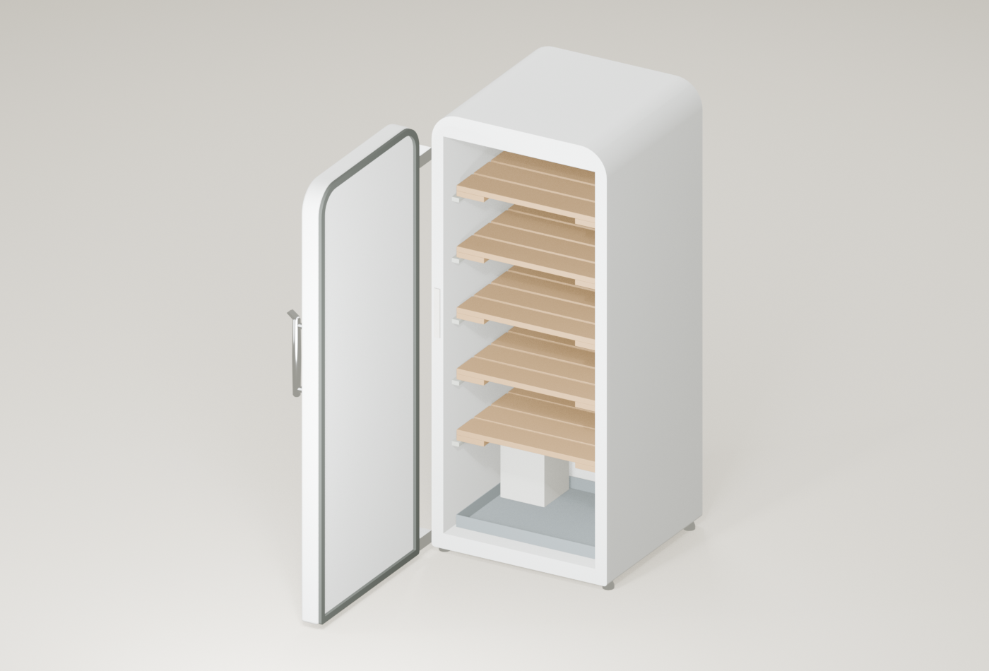
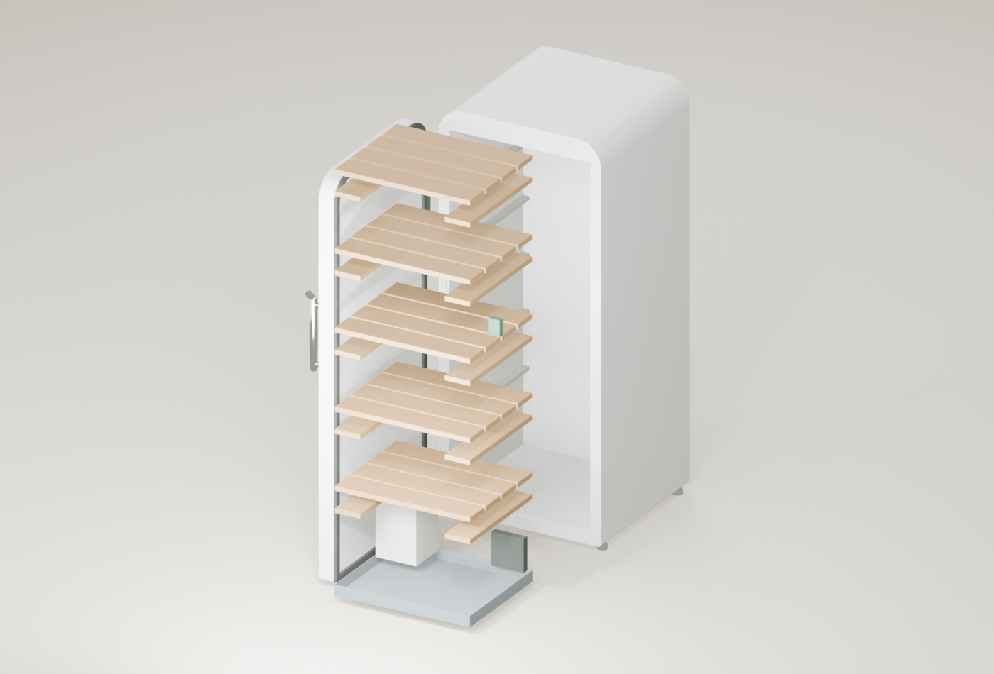
A measured fridge with removable board shelves, a humidifier, fan and sensor, switched by a controller mounted outside.
Default dimensions are shown below. Enable JavaScript to edit dimensions and inspect the 3D model.
Dimensions
- outer Width
- 600 mm
- outer Depth
- 650 mm
- outer Height
- 1,450 mm
- inner Width
- 520 mm
- inner Depth
- 480 mm
- inner Height
- 1,300 mm
- door Thickness
- 70 mm
- freezer Height
- 0 mm
- shelf Spacing
- 200 mm
- wall Clearance
- 10 mm
- door Clearance
- 60 mm
- slat Gap
- 10 mm
- wood Shelves
- 1
- board Thickness
- 18 mm
- board Width
- 94 mm
- board Length
- 2,400 mm
- kerf
- 3 mm
- wheel Diameter
- 150 mm
- wheel Height
- 80 mm
- wheel Gap
- 20 mm
- humidifier Width
- 150 mm
- humidifier Depth
- 150 mm
- humidifier Height
- 200 mm
- humidifier Headroom
- 80 mm
- fan Size
- 120 mm
- heater Count
- 0
Shopping list
Quantities follow the dimensions above and have not been checked against a built example.
| Quantity | Item | Note |
|---|---|---|
| Timber | ||
| 7 2400 mm lengths | untreated wood board18 mm × 94 mm section30 cuts · 2,650 mm offcut in total | First-fit estimate with the entered saw kerf. Check grain and defects before cutting. |
| Fixings and hardware | ||
| 1 kit | cable entry seal kit | Flat seal strip for cables through the door gasket on the hinge side (S2). |
| 40 screws | stainless steel screws | Two per slat, driven up through each batten. Keep them shorter than twice the board thickness; size not specified. |
| Bought parts | ||
| 1 fan | circulation fan | 120 mm square fan. Plugs into the controller; supply and rating not specified. |
| 1 tray | drip tray | At least 500 × 410 mm floor and about 40 mm deep (PROP-001). |
| 1 fridge | fridge (the one you measured) | Reference only. It plugs into the controller, which switches it on and off (S1). |
| 1 humidifier | humidifier | Small unit with its own water tank, no larger than 150 × 150 × 200 mm. Plugs into the controller. |
| 1 instrument | hygrometer with high and low memory | A second reading to check the controller (S1). |
| 1 controller | temperature and humidity controller with sensor | Mounted outside. Switches the fridge, humidifier, fan and heater from its sensor. Check its ratings against every device. |
| Sealants and coatings | ||
| sealant, amount not specified | food-safe silicone sealant | Only if you route cables through a drilled hole instead of the door seal. |
Cutting plan
Stock allocation uses the model’s kerf rule and the default stock lengths. No piece is spliced to fit.
board 1board
2,400 mm- 500 mm
- 500 mm
- 500 mm
- 500 mm
Offcut 388 mm
board 2board
2,400 mm- 500 mm
- 500 mm
- 500 mm
- 500 mm
Offcut 388 mm
board 3board
2,400 mm- 500 mm
- 500 mm
- 500 mm
- 500 mm
Offcut 388 mm
board 4board
2,400 mm- 500 mm
- 500 mm
- 500 mm
- 500 mm
Offcut 388 mm
board 5board
2,400 mm- 500 mm
- 500 mm
- 500 mm
- 500 mm
Offcut 388 mm
board 6board
2,400 mm- 406 mm
- 406 mm
- 406 mm
- 406 mm
- 406 mm
Offcut 355 mm
board 7board
2,400 mm- 406 mm
- 406 mm
- 406 mm
- 406 mm
- 406 mm
Offcut 355 mm
Cut list
| Part | Stock | Cut | Joint and angles |
|---|---|---|---|
| board | 406 mm × 94 mm | Cut and joint details require physical verification. Saw angle from square 0° | |
| board | 406 mm × 94 mm | Cut and joint details require physical verification. Saw angle from square 0° | |
| board | 500 mm × 94 mm | Cut and joint details require physical verification. Saw angle from square 0° | |
| board | 500 mm × 94 mm | Cut and joint details require physical verification. Saw angle from square 0° | |
| board | 500 mm × 94 mm | Cut and joint details require physical verification. Saw angle from square 0° | |
| board | 500 mm × 94 mm | Cut and joint details require physical verification. Saw angle from square 0° | |
| board | 406 mm × 94 mm | Cut and joint details require physical verification. Saw angle from square 0° | |
| board | 406 mm × 94 mm | Cut and joint details require physical verification. Saw angle from square 0° | |
| board | 500 mm × 94 mm | Cut and joint details require physical verification. Saw angle from square 0° | |
| board | 500 mm × 94 mm | Cut and joint details require physical verification. Saw angle from square 0° | |
| board | 500 mm × 94 mm | Cut and joint details require physical verification. Saw angle from square 0° | |
| board | 500 mm × 94 mm | Cut and joint details require physical verification. Saw angle from square 0° | |
| board | 406 mm × 94 mm | Cut and joint details require physical verification. Saw angle from square 0° | |
| board | 406 mm × 94 mm | Cut and joint details require physical verification. Saw angle from square 0° | |
| board | 500 mm × 94 mm | Cut and joint details require physical verification. Saw angle from square 0° | |
| board | 500 mm × 94 mm | Cut and joint details require physical verification. Saw angle from square 0° | |
| board | 500 mm × 94 mm | Cut and joint details require physical verification. Saw angle from square 0° | |
| board | 500 mm × 94 mm | Cut and joint details require physical verification. Saw angle from square 0° | |
| board | 406 mm × 94 mm | Cut and joint details require physical verification. Saw angle from square 0° | |
| board | 406 mm × 94 mm | Cut and joint details require physical verification. Saw angle from square 0° | |
| board | 500 mm × 94 mm | Cut and joint details require physical verification. Saw angle from square 0° | |
| board | 500 mm × 94 mm | Cut and joint details require physical verification. Saw angle from square 0° | |
| board | 500 mm × 94 mm | Cut and joint details require physical verification. Saw angle from square 0° | |
| board | 500 mm × 94 mm | Cut and joint details require physical verification. Saw angle from square 0° | |
| board | 406 mm × 94 mm | Cut and joint details require physical verification. Saw angle from square 0° | |
| board | 406 mm × 94 mm | Cut and joint details require physical verification. Saw angle from square 0° | |
| board | 500 mm × 94 mm | Cut and joint details require physical verification. Saw angle from square 0° | |
| board | 500 mm × 94 mm | Cut and joint details require physical verification. Saw angle from square 0° | |
| board | 500 mm × 94 mm | Cut and joint details require physical verification. Saw angle from square 0° | |
| board | 500 mm × 94 mm | Cut and joint details require physical verification. Saw angle from square 0° |
Openings and fitted details
- id
- cable.entry
- type
- door-seal entry
- centre
- 20 mm, -2 mm, 793 mm
- status
- flat seal strip in line with the door gasket, hinge side (S2); no drilling
- id
- cable.sensor
- type
- cable route
- points
- 530 mm, 265 mm, 823 mm, 20 mm, -2 mm, 793 mm, 0 mm, -2 mm, 793 mm, 0 mm, 100 mm, 1,013 mm
- status
- route proposed; cable length, plug size and ratings not specified
- id
- cable.humidifier
- type
- cable route
- points
- 137 mm, 383 mm, 177 mm, 20 mm, -2 mm, 793 mm, 0 mm, -2 mm, 793 mm, 0 mm, 100 mm, 1,013 mm
- status
- route proposed; cable length, plug size and ratings not specified
- id
- cable.fan
- type
- cable route
- points
- 478 mm, 446 mm, 137 mm, 20 mm, -2 mm, 793 mm, 0 mm, -2 mm, 793 mm, 0 mm, 100 mm, 1,013 mm
- status
- route proposed; cable length, plug size and ratings not specified
- id
- cable.fridge
- type
- mains lead
- status
- the fridge plugs into the controller outside (S1); the fridge keeps its own lead and thermostat
Parts
| Part | Material | Size | Basis |
|---|---|---|---|
| reference fridge | 40 mm × 580 mm × 1,450 mm | measured reference, not cut | |
| reference fridge | 40 mm × 580 mm × 1,450 mm | measured reference, not cut | |
| reference fridge | 520 mm × 580 mm × 75 mm | measured reference, not cut | |
| reference fridge | 520 mm × 580 mm × 75 mm | measured reference, not cut | |
| reference fridge | 520 mm × 100 mm × 1,300 mm | measured reference, not cut | |
| reference fridge | 70 mm × 600 mm × 1,450 mm | measured reference, not cut; drawn open on a left hand hinge | |
| untreated wood board | 94 mm × 406 mm × 18 mm | derived from inside depth, door clearance and slat count | |
| untreated wood board | 94 mm × 406 mm × 18 mm | derived from inside depth, door clearance and slat count | |
| untreated wood board | 500 mm × 94 mm × 18 mm | derived from inside width and wall clearance | |
| untreated wood board | 500 mm × 94 mm × 18 mm | derived from inside width and wall clearance | |
| untreated wood board | 500 mm × 94 mm × 18 mm | derived from inside width and wall clearance | |
| untreated wood board | 500 mm × 94 mm × 18 mm | derived from inside width and wall clearance | |
| untreated wood board | 94 mm × 406 mm × 18 mm | derived from inside depth, door clearance and slat count | |
| untreated wood board | 94 mm × 406 mm × 18 mm | derived from inside depth, door clearance and slat count | |
| untreated wood board | 500 mm × 94 mm × 18 mm | derived from inside width and wall clearance | |
| untreated wood board | 500 mm × 94 mm × 18 mm | derived from inside width and wall clearance | |
| untreated wood board | 500 mm × 94 mm × 18 mm | derived from inside width and wall clearance | |
| untreated wood board | 500 mm × 94 mm × 18 mm | derived from inside width and wall clearance | |
| untreated wood board | 94 mm × 406 mm × 18 mm | derived from inside depth, door clearance and slat count | |
| untreated wood board | 94 mm × 406 mm × 18 mm | derived from inside depth, door clearance and slat count | |
| untreated wood board | 500 mm × 94 mm × 18 mm | derived from inside width and wall clearance | |
| untreated wood board | 500 mm × 94 mm × 18 mm | derived from inside width and wall clearance | |
| untreated wood board | 500 mm × 94 mm × 18 mm | derived from inside width and wall clearance | |
| untreated wood board | 500 mm × 94 mm × 18 mm | derived from inside width and wall clearance | |
| untreated wood board | 94 mm × 406 mm × 18 mm | derived from inside depth, door clearance and slat count | |
| untreated wood board | 94 mm × 406 mm × 18 mm | derived from inside depth, door clearance and slat count | |
| untreated wood board | 500 mm × 94 mm × 18 mm | derived from inside width and wall clearance | |
| untreated wood board | 500 mm × 94 mm × 18 mm | derived from inside width and wall clearance | |
| untreated wood board | 500 mm × 94 mm × 18 mm | derived from inside width and wall clearance | |
| untreated wood board | 500 mm × 94 mm × 18 mm | derived from inside width and wall clearance | |
| untreated wood board | 94 mm × 406 mm × 18 mm | derived from inside depth, door clearance and slat count | |
| untreated wood board | 94 mm × 406 mm × 18 mm | derived from inside depth, door clearance and slat count | |
| untreated wood board | 500 mm × 94 mm × 18 mm | derived from inside width and wall clearance | |
| untreated wood board | 500 mm × 94 mm × 18 mm | derived from inside width and wall clearance | |
| untreated wood board | 500 mm × 94 mm × 18 mm | derived from inside width and wall clearance | |
| untreated wood board | 500 mm × 94 mm × 18 mm | derived from inside width and wall clearance | |
| drip tray | 500 mm × 410 mm × 2 mm | bought tray; footprint derived, rim PROP 001 | |
| drip tray | 500 mm × 2 mm × 38 mm | bought tray; footprint derived, rim PROP 001 | |
| drip tray | 500 mm × 2 mm × 38 mm | bought tray; footprint derived, rim PROP 001 | |
| drip tray | 2 mm × 406 mm × 38 mm | bought tray; footprint derived, rim PROP 001 | |
| drip tray | 2 mm × 406 mm × 38 mm | bought tray; footprint derived, rim PROP 001 | |
| humidifier | 150 mm × 150 mm × 200 mm | bought; envelope measured by the builder | |
| circulation fan | 120 mm × 25 mm × 120 mm | bought; size entered, frame depth PROP 003 | |
| controller sensor | 40 mm × 20 mm × 60 mm | location of the sensor tip; envelope PROP 005 | |
| cable entry seal | 20 mm × 4 mm × 160 mm | hinge side gasket position from S2; strip size PROP 008 | |
| controller mounting position | 20 mm × 120 mm × 180 mm | mounting area on the outside hinge side wall; PROP 007, not the device |
Build steps and tools
Measure the fridge
Measure the outside width, depth and height, the inside width, depth and height, the door thickness and any freezer box. Note the heights of the shelf supports. Enter the measurements and set the shelf spacing to match the supports.
Tape measure.
tape measureCut the slats and battens
Measure your boards and enter their thickness, width and length. Mark the slats and battens from the cut list and crosscut them square. Use untreated wood with no finish.
Pencil, square and a saw for crosscuts: hand crosscut saw, pull saw or mitre saw.
marking pencilsquarehand crosscut sawryoba sawmitre sawAssemble each shelf
Sand the cut ends and edges. Lay the slats face down at the entered gap, set a batten across each end and screw up through the battens with two stainless screws per slat. Drill pilot holes so the slats do not split.
Sander, drill/driver, drill bit and driver bit.
sanderdrill driverdrill bitdriver bitPlace the tray and devices
Set the drip tray on the floor. Stand the humidifier in the back left corner and the fan in the back right corner, and the heater at the front right if you fit one. Slide in the shelves, lowest first, and check that each lifts out.
No tools; check the clearances against the model.
Route the cables
Mount the controller outside on the hinge side. Stick the flat cable-entry seal in line with the door gasket on the hinge side, pass the sensor and device cables through it and coil any extra cable inside. Clip the sensor at shelf level on the side away from the humidifier. Plug the fridge, humidifier, fan and heater into the controller.
Utility knife to trim the seal strip. A competent person checks the wiring and the ratings of every device.
utility knifeCheck before use
Run the cave empty. Compare the controller reading with a separate thermometer and hygrometer at shelf level, look for condensation and water on the floor, and check the door still closes on the seal. Choose temperature and humidity from a recipe or a cheesemaking source; this model sets none.
Temperature and humidity instrument.
hygrometer
Tools by operation
measure fridge
Measure the fridge outside and inside, the door, any freezer box and the heights of its shelf supports
cut slats and battens
Crosscut slats to the shelf width and battens to the shelf depth from the board stock
ease edges
Sand cut ends and edges smooth; leave the wood unfinished
join shelves
Screw each slat to the two end battens from underneath, with pilot holes
route cables
Fit the flat cable-entry seal on the hinge side of the door gasket and fix the sensor at shelf level
check readings
Compare the controller reading with a separate temperature and humidity instrument at shelf level
Before you build
Sealing, condensation, the electrical safety of devices in a cold, humid space and the food process are on the builder; a competent person does any mains wiring. Check the shelf heights against the fridge supports and the shelf load before use.
- Sealing, condensation, the electrical safety of devices in a cold, humid space and the food process are on the builder; a competent person does any mains wiring. Check the shelf heights against the fridge supports and the shelf load before use.
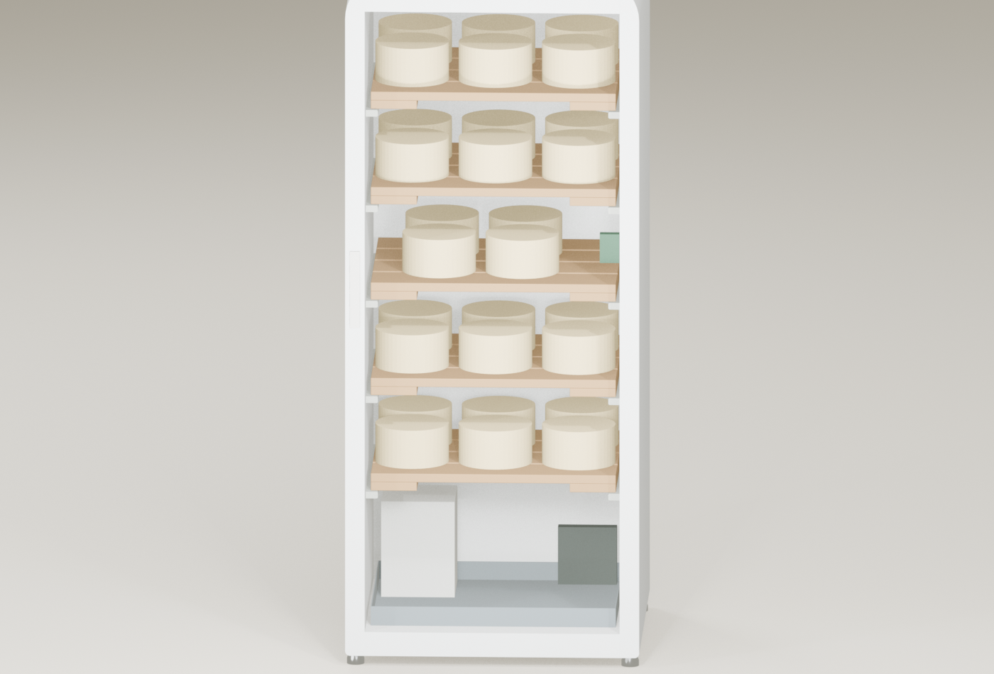
- The fridge is a white reference drawn from your measurements, door open; its rounded top, feet, badge, lights and the ledges under each shelf are drawing details, so check your fridge has supports at those heights. The humidifier, fan, heater, sensor, cable entry and controller are located boxes, not product shapes. Cable routes are listed under fitted details, not drawn. Cheese places are counted, not drawn.
- Whole slats cover 406 mm of the 410 mm shelf depth; the rest is an air gap front and back.
- Shelf heights assume the fridge has supports at those levels. Move a shelf to the nearest support and keep the clear height above each shelf.
What the 3D model leaves out
The fridge is a white reference drawn from your measurements, door open; its rounded top, feet, badge, lights and the ledges under each shelf are drawing details, so check your fridge has supports at those heights. The humidifier, fan, heater, sensor, cable entry and controller are located boxes, not product shapes. Cable routes are listed under fitted details, not drawn. Cheese places are counted, not drawn.
Taking the model apart separates parts for inspection; it is not an assembly order.
Dimension evidence and geometric checks
S1: Converting a Refrigerator to a Cheese Cave; S2: Fridge/Freezer Temperature Probe Installation Kit, installation instructions; S3: ACS Issues Position Statement on the Safety of Aging Cheese on Wood; S4: Biofilm ecology of wooden shelves used in ripening the French raw milk smear cheese Reblochon de Savoie- id
- inside-the-fridge
- ok
- Yes
- detail
- Shelves, tray, devices and sensor stay inside the measured interior below any freezer box.
- id
- no-overlaps
- ok
- Yes
- detail
- No shelf piece, device, sensor or controller position overlaps another.
- id
- cheese-headroom
- ok
- Yes
- detail
- Every shelf has the cheese height plus the space around it clear above.
- id
- humidifier-headroom
- ok
- Yes
- detail
- The lowest shelf sits at least the entered space above the humidifier.
- id
- sensor-away-from-humidifier
- ok
- Yes
- detail
- Sensor sits on the opposite side from the humidifier, 683 mm from the top of it.
- id
- stock-fit
- ok
- Yes
Reference renders
Fixed views of the original proposal. They do not change with your dimensions.