Curing chamber from a fridge
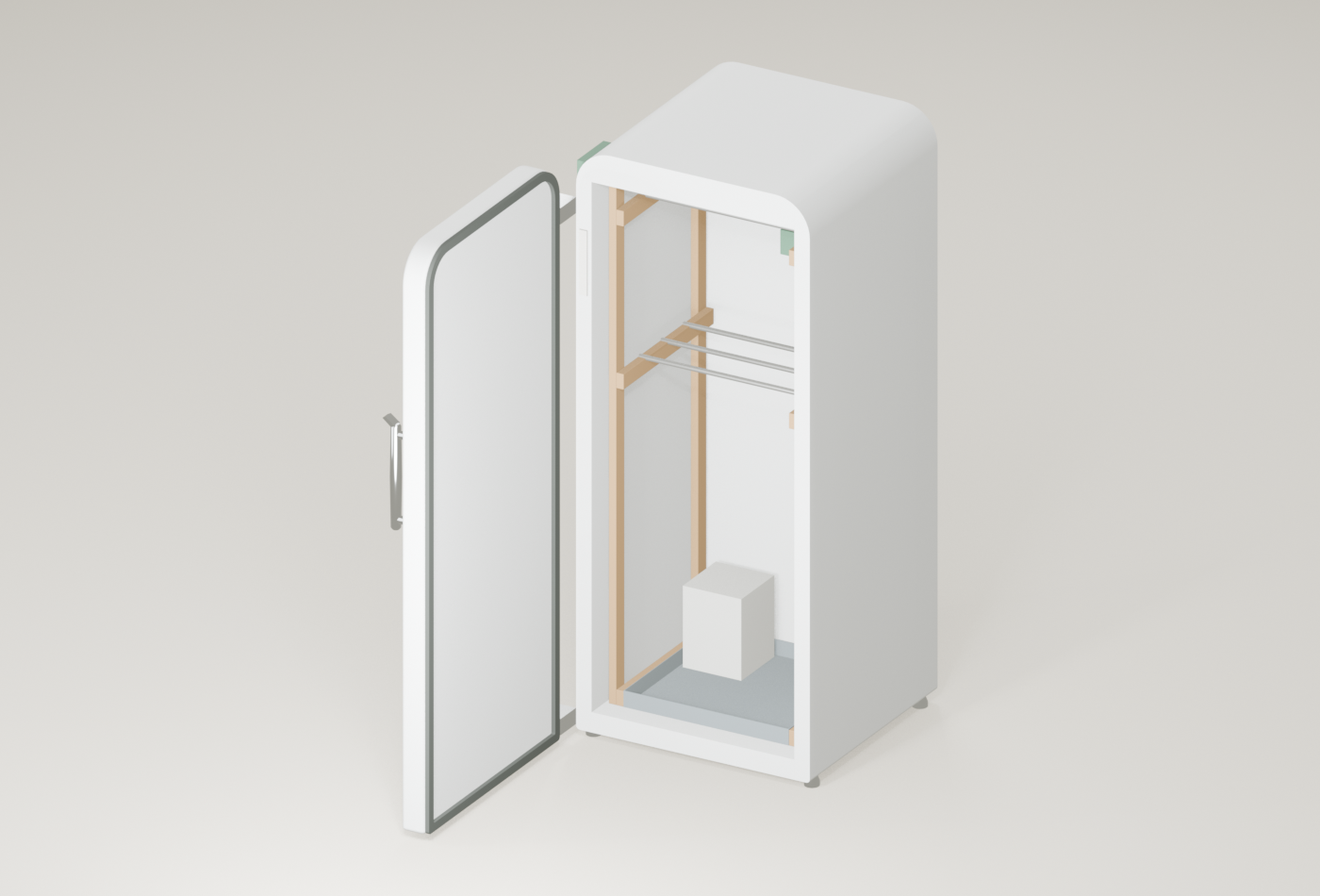
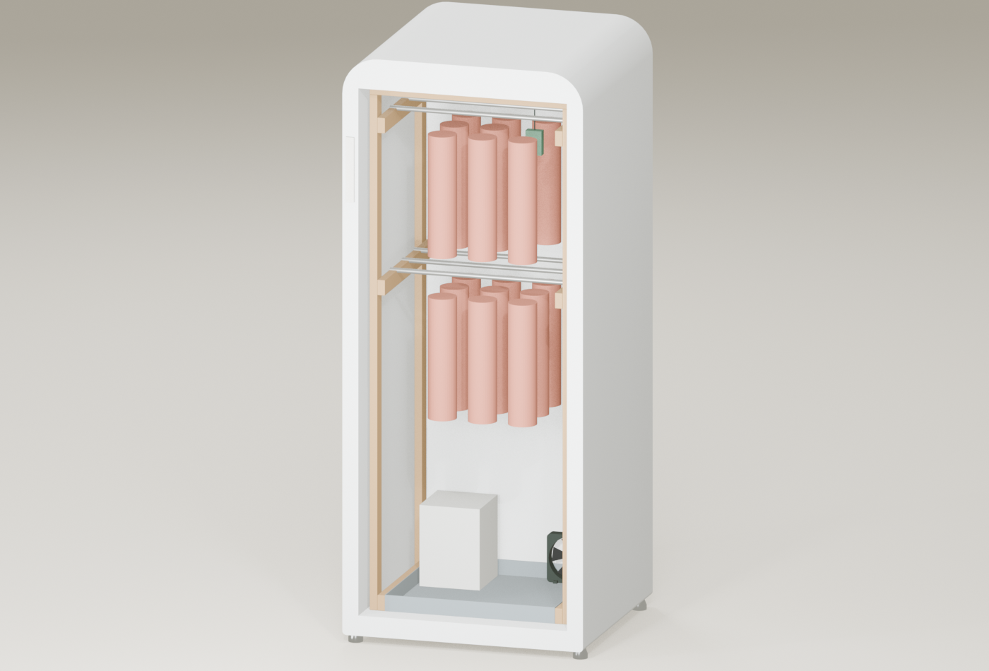
A measured fridge with its shelves out and hanging bars for salami and whole cured meat, a humidifier, fan and sensor, switched by a controller mounted outside.
Default dimensions are shown below. Enable JavaScript to edit dimensions and inspect the 3D model.
Dimensions
- outer Width
- 600 mm
- outer Depth
- 650 mm
- outer Height
- 1,450 mm
- inner Width
- 520 mm
- inner Depth
- 480 mm
- inner Height
- 1,300 mm
- door Thickness
- 70 mm
- freezer Height
- 0 mm
- support Type
- 1
- bar Material
- 1
- bar Diameter
- 12 mm
- drop
- 400 mm
- piece Diameter
- 70 mm
- piece Length
- 300 mm
- piece Gap
- 30 mm
- rail Section
- 19 mm, 38 mm
- board Length
- 2,400 mm
- bar Stock Length
- 1,000 mm
- kerf
- 3 mm
- wall Clearance
- 10 mm
- door Clearance
- 60 mm
- humidifier Width
- 150 mm
- humidifier Depth
- 150 mm
- humidifier Height
- 200 mm
- humidifier Headroom
- 80 mm
- fan Size
- 120 mm
- drying Device
- 0
- heater Count
- 0
Shopping list
Quantities follow the dimensions above and have not been checked against a built example.
| Quantity | Item | Note |
|---|---|---|
| Timber | ||
| 4 2400 mm lengths | untreated timber batten19 mm × 38 mm section12 cuts · 1,020 mm offcut in total | First-fit estimate with the entered saw kerf. Check grain and defects before cutting. |
| Metal lengths | ||
| 3 1000 mm lengths | stainless steel rod12 mm × 12 mm section6 cuts · 222 mm offcut in total | First-fit estimate with the entered saw kerf; the section and material are proposed, not a listed product. |
| Fixings and hardware | ||
| twine, amount not specified | butcher’s twine | To tie and hang pieces without hooks. |
| 1 kit | cable entry seal kit | Flat seal strip for cables through the door gasket on the hinge side (S3). |
| 32 screws | corrosion-resistant wood screws | Two at each joint: rails into the uprights, cross rails down into the upright tops. Length and gauge not specified. |
| 17 hooks | S-hooks | One per piece, hooked over the bar (S1). Material and wire size to choose; or tie each piece with butcher’s twine. |
| Bought parts | ||
| 1 fan | circulation fan | 120 mm square fan on the bottom beside the humidifier (S1). Supply and rating not specified. |
| 1 tray | drip tray | At least 424 × 410 mm floor and about 40 mm deep (PROP-001). |
| 1 fridge | fridge (the one you measured) | Reference only. Shelves out; it plugs into the controller, which switches it on and off (S2). |
| 1 humidifier | humidifier | Ultrasonic (cool-mist) unit, as S1 advises, no larger than 150 × 150 × 200 mm. Plugs into the controller. |
| 1 controller | temperature and humidity controller with sensor | Mounted outside on the hinge-side wall (S1, S2). Switches the fridge, humidifier, fan from its sensor. Check its ratings against every device. |
| 1 instrument | thermo-hygrometer | A second reading among the pieces to check the controller (S1). |
Cutting plan
Stock allocation uses the model’s kerf rule and the default stock lengths. No piece is spliced to fit.
batten 1batten
2,400 mm- 1,271 mm
- 500 mm
- 500 mm
Offcut 120 mm
batten 2batten
2,400 mm- 1,271 mm
- 410 mm
- 410 mm
Offcut 300 mm
batten 3batten
2,400 mm- 1,271 mm
- 410 mm
- 410 mm
Offcut 300 mm
batten 4batten
2,400 mm- 1,271 mm
- 410 mm
- 410 mm
Offcut 300 mm
bar 1bar
1,000 mm- 460 mm
- 460 mm
Offcut 74 mm
bar 2bar
1,000 mm- 460 mm
- 460 mm
Offcut 74 mm
bar 3bar
1,000 mm- 460 mm
- 460 mm
Offcut 74 mm
Cut list
| Part | Stock | Cut | Joint and angles |
|---|---|---|---|
| batten | 1,271 mm × 38 mm | Cut and joint details require physical verification. Saw angle from square 0° | |
| batten | 1,271 mm × 38 mm | Cut and joint details require physical verification. Saw angle from square 0° | |
| batten | 1,271 mm × 38 mm | Cut and joint details require physical verification. Saw angle from square 0° | |
| batten | 1,271 mm × 38 mm | Cut and joint details require physical verification. Saw angle from square 0° | |
| batten | 500 mm × 38 mm | Cut and joint details require physical verification. Saw angle from square 0° | |
| batten | 500 mm × 38 mm | Cut and joint details require physical verification. Saw angle from square 0° | |
| batten | 410 mm × 38 mm | Cut and joint details require physical verification. Saw angle from square 0° | |
| batten | 410 mm × 38 mm | Cut and joint details require physical verification. Saw angle from square 0° | |
| batten | 410 mm × 38 mm | Cut and joint details require physical verification. Saw angle from square 0° | |
| batten | 410 mm × 38 mm | Cut and joint details require physical verification. Saw angle from square 0° | |
| batten | 410 mm × 38 mm | Cut and joint details require physical verification. Saw angle from square 0° | |
| batten | 410 mm × 38 mm | Cut and joint details require physical verification. Saw angle from square 0° | |
| bar | 460 mm × 12 mm | Cut and joint details require physical verification. Saw angle from square 0° | |
| bar | 460 mm × 12 mm | Cut and joint details require physical verification. Saw angle from square 0° | |
| bar | 460 mm × 12 mm | Cut and joint details require physical verification. Saw angle from square 0° | |
| bar | 460 mm × 12 mm | Cut and joint details require physical verification. Saw angle from square 0° | |
| bar | 460 mm × 12 mm | Cut and joint details require physical verification. Saw angle from square 0° | |
| bar | 460 mm × 12 mm | Cut and joint details require physical verification. Saw angle from square 0° |
Openings and fitted details
- id
- cable.entry
- type
- door-seal entry
- centre
- 20 mm, -2 mm, 1,174 mm
- status
- flat seal strip in line with the door gasket, hinge side (S3); cables between door and fridge, no drilling (S2)
- id
- cable.humidifier
- type
- cable route
- points
- 175 mm, 383 mm, 177 mm, 20 mm, -2 mm, 1,174 mm, 0 mm, -2 mm, 1,174 mm, 0 mm, 100 mm, 1,310 mm
- status
- route proposed; cable length, plug size and ratings not specified
- id
- cable.fan
- type
- cable route
- points
- 440 mm, 446 mm, 137 mm, 20 mm, -2 mm, 1,174 mm, 0 mm, -2 mm, 1,174 mm, 0 mm, 100 mm, 1,310 mm
- status
- route proposed; cable length, plug size and ratings not specified
- id
- cable.sensor
- type
- cable route
- points
- 400 mm, 265 mm, 1,204 mm, 20 mm, -2 mm, 1,174 mm, 0 mm, -2 mm, 1,174 mm, 0 mm, 100 mm, 1,310 mm
- status
- route proposed; cable length, plug size and ratings not specified
- id
- cable.fridge
- type
- mains lead
- status
- the fridge plugs into the controller outside (S2); the fridge keeps its own lead and thermostat
Parts
| Part | Material | Size | Basis |
|---|---|---|---|
| reference fridge | 40 mm × 580 mm × 1,450 mm | measured reference, not cut | |
| reference fridge | 40 mm × 580 mm × 1,450 mm | measured reference, not cut | |
| reference fridge | 520 mm × 580 mm × 75 mm | measured reference, not cut | |
| reference fridge | 520 mm × 580 mm × 75 mm | measured reference, not cut | |
| reference fridge | 520 mm × 100 mm × 1,300 mm | measured reference, not cut | |
| reference fridge | 70 mm × 600 mm × 1,450 mm | measured reference, not cut; drawn open on a left hand hinge | |
| untreated timber batten | 19 mm × 38 mm × 1,271 mm | derived from inside height and wall clearance | |
| untreated timber batten | 19 mm × 38 mm × 1,271 mm | derived from inside height and wall clearance | |
| untreated timber batten | 19 mm × 38 mm × 1,271 mm | derived from inside height and wall clearance | |
| untreated timber batten | 19 mm × 38 mm × 1,271 mm | derived from inside height and wall clearance | |
| untreated timber batten | 500 mm × 38 mm × 19 mm | derived from inside width and wall clearance; lies flat on the upright tops | |
| untreated timber batten | 500 mm × 38 mm × 19 mm | derived from inside width and wall clearance; lies flat on the upright tops | |
| untreated timber batten | 19 mm × 410 mm × 38 mm | derived from inside depth and clearances | |
| untreated timber batten | 19 mm × 410 mm × 38 mm | derived from inside depth and clearances | |
| untreated timber batten | 19 mm × 410 mm × 38 mm | derived; screwed to the inside of the uprights | |
| untreated timber batten | 19 mm × 410 mm × 38 mm | derived; screwed to the inside of the uprights | |
| untreated timber batten | 19 mm × 410 mm × 38 mm | derived; screwed to the inside of the uprights | |
| untreated timber batten | 19 mm × 410 mm × 38 mm | derived; screwed to the inside of the uprights | |
| stainless steel rod | 460 mm × 12 mm × 12 mm | derived from the rail spacing; rests in the rail notches | |
| stainless steel rod | 460 mm × 12 mm × 12 mm | derived from the rail spacing; rests in the rail notches | |
| stainless steel rod | 460 mm × 12 mm × 12 mm | derived from the rail spacing; rests in the rail notches | |
| stainless steel rod | 460 mm × 12 mm × 12 mm | derived from the rail spacing; rests in the rail notches | |
| stainless steel rod | 460 mm × 12 mm × 12 mm | derived from the rail spacing; rests in the rail notches | |
| stainless steel rod | 460 mm × 12 mm × 12 mm | derived from the rail spacing; rests in the rail notches | |
| drip tray | 424 mm × 410 mm × 2 mm | bought tray; footprint derived, rim PROP 001 | |
| drip tray | 424 mm × 2 mm × 38 mm | bought tray; footprint derived, rim PROP 001 | |
| drip tray | 424 mm × 2 mm × 38 mm | bought tray; footprint derived, rim PROP 001 | |
| drip tray | 2 mm × 406 mm × 38 mm | bought tray; footprint derived, rim PROP 001 | |
| drip tray | 2 mm × 406 mm × 38 mm | bought tray; footprint derived, rim PROP 001 | |
| humidifier | 150 mm × 150 mm × 200 mm | bought; envelope measured by the builder; on the bottom as in S1 | |
| circulation fan | 120 mm × 25 mm × 120 mm | bought; size entered, frame depth PROP 003; on the bottom beside the humidifier as in S1 | |
| controller sensor | 40 mm × 20 mm × 60 mm | hangs in a piece place on a middle bar; envelope PROP 005 | |
| cable entry seal | 20 mm × 4 mm × 160 mm | hinge side gasket position (S3); strip size PROP 007 | |
| controller mounting position | 20 mm × 120 mm × 180 mm | mounting area on the outside hinge side wall (S1, S2); PROP 006, not the device |
Build steps and tools
Measure the fridge
Take out the shelves and drawers. Measure the outside width, depth and height, the inside width, depth and height, the door thickness and any freezer box. Measure how far the door liner reaches inside and enter it as the clearance to the door.
Tape measure.
tape measureChoose the supports and the pieces
Pick a timber frame that stands inside, timber rails glued to the side walls, or bought tension rods; nothing is drilled through the fridge. Enter the widest and longest piece you plan to hang, the space you want between pieces and the drop between bar levels. The model counts the places.
Cut the timber and bars
Measure your battens and enter their section. Mark the uprights, cross rails, bottom rails and bar rails from the cut list and crosscut them square. Cut the bars to length, stainless rod with a metal-cutting saw and dowel with a fine saw, and smooth the ends. With tension rods there is nothing to cut.
Pencil, square and a saw: hand crosscut saw, pull saw or mitre saw for timber; a metal-cutting saw for rod.
marking pencilsquarehand crosscut sawryoba sawmitre sawsawNotch the bar rails
Clamp the left and right rail of each level together, top edge to top edge. Drill at each notch centre from the cut list on the joint line with a bit the size of the notch diameter. Pulled apart, each rail has half-round notches that line up across the fridge.
Drill/driver, drill bit and clamp.
drill driverdrill bitclampFit the supports
Frame: screw each bar rail and bottom rail to the inside of its front and back uprights through pilot holes, lay the cross rails over the upright tops and screw down, then stand the frame inside. Glued rails: mark the rail heights on both walls and glue each pair level and opposite each other. Tension rods: twist each one out to the inside width at the bar heights and check it holds.
Drill/driver, drill bit and driver bit for the frame; tape measure to mark heights.
drill driverdrill bitdriver bittape measurePlace the tray and devices
Set the drip tray on the floor. Stand the humidifier in the back left corner and the fan in the back right corner, with the dehumidifier or second fan at the front left and the heater at the front right if you fit them. Lay the bars in their notches.
No tools; check the clearances against the model.
Route the cables
Mount the controller outside on the hinge side. Stick the flat cable-entry seal in line with the door gasket on the hinge side, pass the sensor and device cables through it and coil spare cable inside. Hang the sensor from the middle bar in the place the model leaves for it, touching nothing. Plug the fridge and every device into the controller.
Utility knife to trim the seal strip. A competent person checks the wiring and the ratings of every device.
utility knifeCheck before use
Run the chamber empty. Compare the controller reading with a separate thermo-hygrometer among the bars, look for condensation and water in the tray, and check the door still closes on the seal. Hang a loaded bar and check that its supports hold it. Take temperature, humidity, times, weight loss and nitrite use from a tested curing source; this model sets none.
Temperature and humidity instrument.
hygrometer
Tools by operation
measure fridge
Measure the fridge outside and inside, the door, any freezer box and the room the door liner takes
cut timber
Crosscut the uprights, cross rails, bottom rails and bar rails from the batten stock
notch rails
Clamp each pair of bar rails top edge to top edge and drill the bar notches on the joint line
cut bars
Cut the bars to length and smooth the ends
assemble frame
Screw the bar rails and bottom rails to the uprights, then the cross rails across the tops, with pilot holes
route cables
Fit the flat cable-entry seal on the hinge side of the door gasket and hang the sensor where the meat hangs
check readings
Compare the controller reading with a separate temperature and humidity instrument among the hanging pieces
Before you build
The curing process, nitrite use, mould management and the electrical safety of devices in a cold, humid space are on the builder; a competent person does any mains wiring. Check that the bars and their supports carry your load and that the door still seals over the cable strip.
- The curing process, nitrite use, mould management and the electrical safety of devices in a cold, humid space are on the builder; a competent person does any mains wiring. Check that the bars and their supports carry your load and that the door still seals over the cable strip.
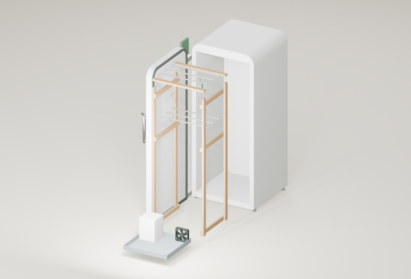
- The fridge is a white reference drawn from your measurements, door open; its rounded top, feet, badge and lights are drawing details. Bars are drawn round; the rail notches are in the cut list, not cut in the 3D view. The fans are drawn standing on feet and the sensor on its cord; the humidifier, dehumidifier, heater, cable entry and controller are located boxes. None of these is a product shape. Hanging places are counted, not drawn.
- S1 keeps wood out of a curing chamber because the damp air favours mould. The frame, rails are timber here; how you clean, dry and replace them is your call.
- The frame stands on the fridge floor. If the floor steps up over the compressor at the back, the back uprights need cutting to suit; the model assumes a flat floor.
- The model does not check the load on the bars. S1 notes that a large ham can weigh 25-30 lb, while sausages need much less.
What the 3D model leaves out
The fridge is a white reference drawn from your measurements, door open; its rounded top, feet, badge and lights are drawing details. Bars are drawn round; the rail notches are in the cut list, not cut in the 3D view. The fans are drawn standing on feet and the sensor on its cord; the humidifier, dehumidifier, heater, cable entry and controller are located boxes. None of these is a product shape. Hanging places are counted, not drawn.
Taking the model apart separates parts for inspection; it is not an assembly order.
Dimension evidence and geometric checks
S1: How to Convert a Refrigerator for Curing Meat or Aging Cheese; S2: Advanced Meat Curing Chamber At Home; S3: Fridge/Freezer Temperature Probe Installation Kit, installation instructions; S4: Olpro Telescopic Cupboard & Fridge Storage Bars 41-71cm, pack of two- id
- inside-the-fridge
- ok
- Yes
- detail
- Frame, rails, bars, tray, devices and sensor stay inside the measured interior below any freezer box.
- id
- no-overlaps
- ok
- Yes
- detail
- No frame piece, rail, bar, device, sensor or controller position overlaps another; bars rest in their rail notches.
- id
- pieces-above-devices
- ok
- Yes
- detail
- The lowest pieces end at least the space between pieces above the humidifier headroom and the other devices.
- id
- levels-clear
- ok
- Yes
- detail
- Each level of pieces ends at least the space between pieces above the bars below it.
- id
- room-to-lift-hooks
- ok
- Yes
- detail
- There is a hook length of room above the top bars to lift the hooks off.
- id
- sensor-away-from-humidifier
- ok
- Yes
- detail
- The sensor hangs on the side away from the humidifier, 961 mm from the top of it.
- id
- stock-fit
- ok
- Yes
Reference renders
Fixed views of the original proposal. They do not change with your dimensions.