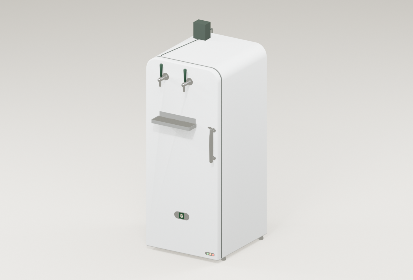
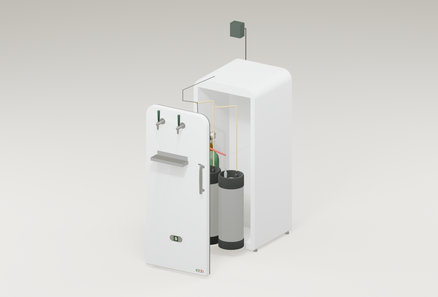
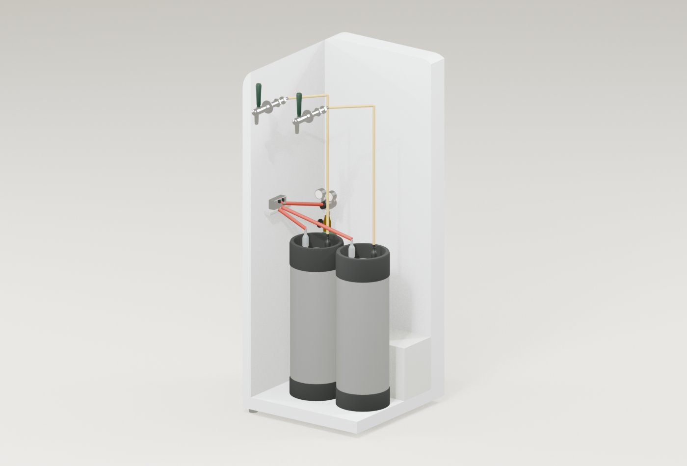
Kegerator from an upright fridge
A fridge you already have, with taps through the door, kegs and CO2 inside and a temperature controller.
Default dimensions are shown below. Enable JavaScript to edit dimensions and inspect the 3D model.
Dimensions
- outer Width
- 600 mm
- outer Depth
- 650 mm
- outer Height
- 1,450 mm
- door Thickness
- 60 mm
- interior Width
- 520 mm
- interior Depth
- 500 mm
- interior Height
- 1,300 mm
- step Depth
- 180 mm
- step Height
- 220 mm
- top Compartment
- 0 mm
- door Shelf Depth
- 100 mm
- keg Diameter
- 216 mm
- keg Height
- 635 mm
- coupler Clearance
- 100 mm
- tap Count
- 2
- tap Height
- 1,330 mm
- tap Spacing
- 0 mm
- shank Diameter
- 22 mm
- handle Side
- 2
- handle Zone
- 70 mm
- cylinder Diameter
- 133 mm
- cylinder Height
- 445 mm
- cylinder Place
- 1
Shopping list
Quantities follow the dimensions above and have not been checked against a built example.
| Quantity | Item | Note |
|---|---|---|
| Fixings and hardware | ||
| 10 clamps | Hose clamps | Two per line run; size them to the line |
| Bought parts | ||
| 2.3 m | Beer line | 1.1 m, 1.3 m per tap, reach with the door open |
| 2 shanks | Beer shanks, 101.6 mm long, 22.2 mm diameter | Shortest listed length for a 60 mm door |
| 1 cylinder | CO2 cylinder | 133 × 445 mm as entered, on the compressor step |
| 1 regulator | CO2 regulator | To fit the cylinder valve |
| 1 tray | Drip tray, door mount | About 318.013 mm long, top 1025.2 mm above the floor |
| 2 faucets | Faucets | To fit the shank thread |
| 1.3 m | Gas line | 3 runs, route plus 200 mm each |
| 1 manifold | Gas manifold, 2 outlets | With a shut-off on each outlet |
| 1 saw | Hole saw, 22.2 mm | Smallest common size over the shank diameter; the shank maker’s instructions decide |
| 2 sets | Keg couplers or ball-lock disconnect pairs | Match the keg valve type |
| 2 kegs | Kegs | 216 × 635 mm as entered; 2 fit on the floor |
| 2 handles | Tap handles | 198.013 mm between tap centres |
| 1 controller | Temperature controller with probe | Switches the fridge on and off; rated for the fridge. Wiring is for a competent person. |
| 1 fridge | Upright fridge | Your fridge, drawn from your measurements. Check its door for wiring and cooling lines before buying parts. |
| Sealants and coatings | ||
| sealant, amount not specified | Sealant or sleeve for the cut foam | Close off the foam in each hole. Builders report sleeves, foil tape and foam; none is a tested method. |
Cutting plan
Stock allocation uses the model’s kerf rule and the default stock lengths. No piece is spliced to fit.
No stock allocation is available for this model.
Cut list
| Part | Stock | Cut | Joint and angles |
|---|
Openings and fitted details
- id
- door.shank-hole.1
- type
- circle
- diameter
- 22 mm
- centre
- 166 mm, 30 mm, 1,330 mm
- axis
- y
- status
- hole-saw size over the shank diameter
- id
- door.shank-hole.2
- type
- circle
- diameter
- 22 mm
- centre
- 364 mm, 30 mm, 1,330 mm
- axis
- y
- status
- hole-saw size over the shank diameter
Parts
| Part | Material | Size | Basis |
|---|---|---|---|
| fridge cabinet | 40 mm × 590 mm × 1,450 mm | measured by you | |
| fridge cabinet | 40 mm × 590 mm × 1,450 mm | measured by you | |
| fridge cabinet | 520 mm × 90 mm × 1,450 mm | measured by you | |
| fridge cabinet | 520 mm × 500 mm × 75 mm | measured by you | |
| fridge cabinet | 520 mm × 500 mm × 75 mm | measured by you | |
| fridge cabinet | 520 mm × 180 mm × 220 mm | measured by you | |
| fridge door | 600 mm × 60 mm × 1,450 mm | measured by you | |
| fridge door handle | 28 mm × 28 mm × 260 mm | drawn marker inside your handle zone | |
| fridge hinge | 24 mm × 24 mm × 50 mm | drawn marker at the hinge edge | |
| fridge hinge | 24 mm × 24 mm × 50 mm | drawn marker at the hinge edge | |
| shank flange | 54 mm × 5 mm × 54 mm | Keg Booty step 2: a 2 1/8 in flange covers the shank hole | |
| beer shank | 22 mm × 102 mm × 22 mm | 101 6 mm: shortest listed length for the door | |
| faucet | 28 mm × 74 mm × 28 mm | drawn size; check your faucet | |
| tap handle | 24 mm × 24 mm × 100 mm | drawn size | |
| shank flange | 54 mm × 5 mm × 54 mm | Keg Booty step 2: a 2 1/8 in flange covers the shank hole | |
| beer shank | 22 mm × 102 mm × 22 mm | 101 6 mm: shortest listed length for the door | |
| faucet | 28 mm × 74 mm × 28 mm | drawn size; check your faucet | |
| tap handle | 24 mm × 24 mm × 100 mm | drawn size | |
| drip tray | 318 mm × 100 mm × 25 mm | American Homestead: drip tray about one foot below the tap | |
| CO2 cylinder | 133 mm × 133 mm × 445 mm | your cylinder, measured with its valve | |
| CO2 regulator | 90 mm × 70 mm × 110 mm | drawn size; the allowance above the valve is a proposal | |
| gas manifold | 30 mm × 80 mm × 40 mm | drawn size; rest or hang it without screwing into the walls | |
| gas line | 61 mm × 220 mm × 70 mm | drawn route; cut length in the list | |
| gas line | 103 mm × 71 mm × 92 mm | drawn route; cut length in the list | |
| gas line | 322 mm × 47 mm × 95 mm | drawn route; cut length in the list | |
| beer keg | 216 mm × 216 mm × 635 mm | your keg, measured | |
| keg coupler | 26 mm × 26 mm × 72 mm | drawn size inside the coupler clearance | |
| beer line | 11 mm × 11 mm × 580 mm | drawn route; cut length in the list | |
| beer line | 112 mm × 132 mm × 11 mm | drawn route; cut length in the list | |
| beer keg | 216 mm × 216 mm × 635 mm | your keg, measured | |
| keg coupler | 26 mm × 26 mm × 72 mm | drawn size inside the coupler clearance | |
| beer line | 11 mm × 11 mm × 580 mm | drawn route; cut length in the list | |
| beer line | 140 mm × 133 mm × 11 mm | drawn route; cut length in the list | |
| temperature controller | 100 mm × 70 mm × 120 mm | generic controller; drawn size for location only | |
| temperature probe | 8 mm × 8 mm × 40 mm | position proposed: taped to the front of keg 1 | |
| probe lead | 55 mm × 428 mm × 5 mm | route proposed: over the top and under the hinge side gasket | |
| probe lead | 5 mm × 5 mm × 95 mm | route proposed: over the top and under the hinge side gasket | |
| probe lead | 127 mm × 32 mm × 5 mm | route proposed: over the top and under the hinge side gasket | |
| probe lead | 5 mm × 65 mm × 928 mm | route proposed: over the top and under the hinge side gasket | |
| fridge power lead | 8 mm × 8 mm × 1,330 mm | fridge plug into the controller socket; mains wiring is not designed here | |
| fridge power lead | 8 mm × 100 mm × 8 mm | fridge plug into the controller socket; mains wiring is not designed here |
Build steps and tools
Measure the fridge
Unplug the fridge and empty it. Measure outside width, depth with the door and height, the door thickness at the tap position, the inside with the shelves out, the compressor step, any top compartment and how far the door shelves stand in. Enter them above; the model then tells you how many kegs fit and where the taps go.
Tape measure and pencil.
tape measuremarking pencilCheck the door before drilling
Find out whether the door carries wiring (a display, light switch or dispenser) or cooling lines: read the manual or wiring diagram and search the model number with “kegerator” for earlier conversions. If you find either, do not drill that door. Otherwise drill a small pilot through the inner plastic liner only at a tap centre and probe the foam behind it with a thin screwdriver or nail.
Drill/driver with a small bit and a screwdriver. Do not use an impact driver on the liner.
drill driverdrill bitscrewdriverMark and cut the holes
Take out the door shelves. Mark each tap centre on the outer skin at the height and spacing the model gives, and check it against the pilot. Cut each shank hole with the listed hole saw, slowly and with eye protection. With the cylinder outside, cut the gas-line hole near the hinge as well.
Hole saw on a drill/driver; a utility knife trims the liner edge.
hole sawdrill driverutility knifeSeal the cut foam
Close off the exposed foam in every hole before the shank goes in, so the door insulation is not left open. Builders line the hole with a short sleeve, foil tape or sealant; choose one and check it is suited to the inside of a fridge.
Utility knife to trim the sleeve or tape.
utility knifeFit the taps and drip tray
Push each shank through from the front with its flange on the outside, then tighten the locknut on the inside with a spanner. Fit the faucets and handles. Fix the drip tray at the height the model gives, with fixings that stay clear of anything you found in the door.
Screwdriver or drill/driver for the tray; a spanner or faucet wrench for the nuts, which the tool list does not include.
screwdriverdrill driverPlace the kegs and gas
Stand the kegs where the model shows. Set the cylinder upright on the step, on the floor, or outside next to the hinge, and secure it so it cannot fall. Fit the regulator, then the manifold for more than one keg; rest or hang the manifold without screwing into the side or back walls, which can hold cooling lines.
Screwdriver for hose clamps; pliers to hold fittings.
screwdriverpliersRun the beer and gas lines
Cut each beer line to at least the length listed for its tap, which allows for the door opening. Connect it from the coupler to the shank tail and clamp both ends. Run the gas lines from the regulator to the manifold and on to each keg, and clamp them.
Utility knife to cut lines square; screwdriver for the clamps.
utility knifescrewdriverFit the temperature controller
Set the controller on top of the cabinet at the back hinge corner. Tape its probe to the front of keg 1 and lead the probe cable over the top and under the door seal on the hinge side; check the door still closes and seals. Plug the fridge into the controller and the controller into the wall socket. A competent person handles any wiring.
No tools needed for a plug-in controller.
Check before you fill
Check every gas joint for leaks the way the regulator and coupler makers describe. Open and close the door with all lines connected to make sure nothing pulls tight or catches. Serving temperature, gas pressure and drink handling are yours to set from the keg and equipment makers’ instructions.
Tools by operation
measure fridge
Measure the fridge outside and inside, the door, the compressor step, any top compartment and the door shelves
check door
Find out whether the door holds wiring or cooling lines, then drill a small pilot through the inner liner and probe the foam
cut tap holes
Cut the shank holes, and the gas-line hole when the cylinder stands outside, with the listed hole saws
seal foam
Close off the cut foam in every hole before fitting the shanks
fit door parts
Fit shanks, faucets, handles and the drip tray; the shank locknut needs a spanner, which the tool catalogue does not list
run lines
Cut beer and gas lines to the listed lengths and clamp them to the couplers, shanks, manifold and regulator
Before you build
Before drilling, find out whether the door holds wiring or cooling lines, and seal the cut foam in every hole. CO2 handling, the controller and its wiring, and serving the drink are for you, with a competent person for the mains side.
- Before drilling, find out whether the door holds wiring or cooling lines, and seal the cut foam in every hole. CO2 handling, the controller and its wiring, and serving the drink are for you, with a competent person for the mains side.
- The fridge is drawn from your measurements as a white appliance and is never cut; its rounded top, feet, badge and lights are drawing details. Faucets, kegs, couplers, regulator and controller are drawn at nominal sizes to show where they go. Lines are straight runs between their ends; real lines curve and need the listed slack.
- Take out the door shelves: with them fitted, no keg fits.
- CO2 cylinder on the compressor step.
- Line lengths cover reach only. The length that balances pour speed depends on line bore, pressure and temperature, which this model does not set.
What the 3D model leaves out
The fridge is drawn from your measurements as a white appliance and is never cut; its rounded top, feet, badge and lights are drawing details. Faucets, kegs, couplers, regulator and controller are drawn at nominal sizes to show where they go. Lines are straight runs between their ends; real lines curve and need the listed slack.
Taking the model apart separates parts for inspection; it is not an assembly order.
Dimension evidence and geometric checks
Original layout over a fridge you measure- id
- kegs-inside
- ok
- Yes
- id
- keg-height
- ok
- Yes
- detail
- 565 mm spare above the couplers
- id
- taps-clear-of-edges
- ok
- Yes
- id
- tap-spacing
- ok
- Yes
- detail
- 198 mm centres
- id
- shank-through-door
- ok
- Yes
- id
- drip-tray-on-door
- ok
- Yes
- id
- positive-dimensions
- ok
- Yes
Reference renders
Fixed views of the original proposal. They do not change with your dimensions.