Koji and tempeh incubator
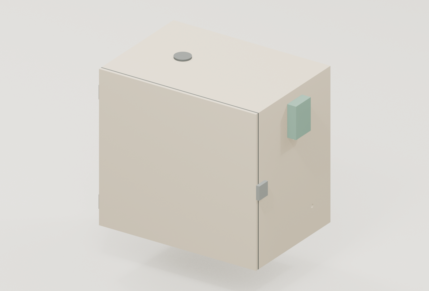
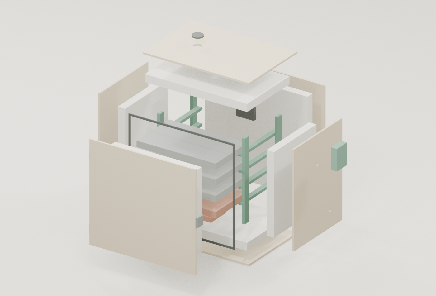
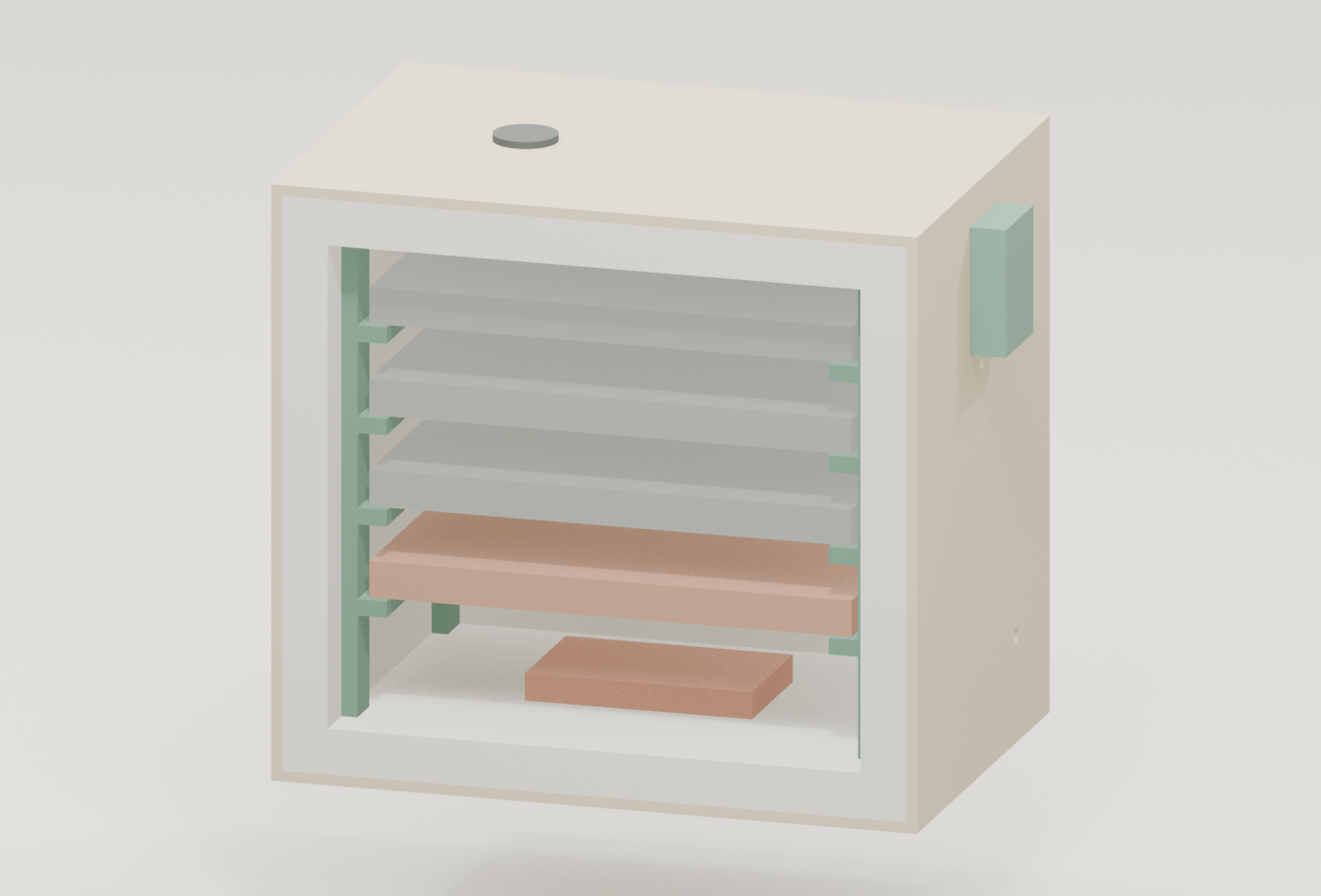
An insulated plywood cabinet sized from your trays, with runners, a water pan, and spaces for a heater, fan and controller.
Default dimensions are shown below. Enable JavaScript to edit dimensions and inspect the 3D model.
Dimensions
- tray Length
- 530 mm
- tray Width
- 325 mm
- tray Height
- 40 mm
- tray Count
- 3
- tray Spacing
- 100 mm
- side Clearance
- 10 mm
- back Clearance
- 40 mm
- insulation
- 50 mm
- foam Sheet
- 1,200 mm, 2,400 mm
- plywood
- 12 mm
- upright Section
- 18 mm, 44 mm
- runner Section
- 18 mm, 32 mm
- timber Length
- 2,400 mm
- sheet
- 1,220 mm, 2,440 mm
- kerf
- 3 mm
- seal Thickness
- 6 mm
- heater Length
- 250 mm
- heater Width
- 150 mm
- heater Height
- 30 mm
- heater Clearance
- 100 mm
- fan Size
- 120 mm
- vent Diameter
- 50 mm
- port Diameter
- 16 mm
Shopping list
Quantities follow the dimensions above and have not been checked against a built example.
| Quantity | Item | Note |
|---|---|---|
| Timber | ||
| 1 2400 mm length | planed softwood18 mm × 44 mm section · rack uprights4 cuts · 268 mm offcut in total | First-fit estimate with the entered saw kerf. Check grain and defects before cutting. |
| 2 2400 mm lengths | planed softwood18 mm × 32 mm section · tray runners8 cuts · 1,776 mm offcut in total | |
| Sheet | ||
| 1 sheet | PIR or XPS insulation board1,200 mm × 2,400 mm sheet6 panels placed with the entered kerf | Individual placement, not a full nesting plan. |
| 2 sheets | plywood1,220 mm × 2,440 mm sheet6 panels placed with the entered kerf | |
| Fixings and hardware | ||
| 2 hinges | Door hinges | Surface hinges that clear the 6 mm seal; type not selected. |
| 2.7 m | Door seal, compressible strip | 6 mm thick, up to 12 mm wide, on the plywood front edges. |
| 1 latch | Toggle latch | Pulls the door onto the seal; type not selected. |
| 36 screws | Wood screws, 40 mm | Carcass joints at about 150 mm spacing; drill pilot holes. |
| 32 screws | Wood screws, 45 mm | Runners to uprights, 2 at each end. |
| 12 screws | Wood screws, 75 mm | Uprights through the insulation into the sides; length stops short of the outside face. |
| Bought parts | ||
| 1 vent | Adjustable vent, 50 mm | Round vent with a slide or twist cover over a 50 mm hole in the top. |
| 1 fan | Circulation fan, 120 mm | Space for a 120 mm square, 25 mm deep fan on the back lining. |
| 1 controller | Controller (reads temperature and humidity, switches heater and fan) | Mounting position outside on the right side, about 40 × 100 × 140 mm. No controller is specified. |
| 3 trays | Food trays the cabinet is sized for | 530 × 325 × 40 mm. Use the trays you have; the whole cabinet is sized from them. |
| 1 heater | Heater: heat mat or low-wattage element | Space 250 × 150 × 30 mm. Choose the product and its rating separately; a competent person wires it. |
| 1 pan | Water pan | Same size as one tray; sits on the lowest runners. |
| Sealants and coatings | ||
| 1.77 m² | Adhesive suitable for PIR or XPS | Area of insulation face to bond. Buy for this area at the product’s stated coverage. |
| 8.4 m | Aluminium foil tape | Inside corner joints of the lining, the front edge of the opening and the door plug edges. |
| 5.1 m | Flexible sealant | Bead length along the inside plywood joints and around the vent and ports. |
Cutting plan
Stock allocation uses the model’s kerf rule and the default stock lengths. No piece is spliced to fit.
upright 1upright
2,400 mm- 530 mm
- 530 mm
- 530 mm
- 530 mm
Offcut 268 mm
runner 1runner
2,400 mm- 375 mm
- 375 mm
- 375 mm
- 375 mm
- 375 mm
- 375 mm
Offcut 132 mm
runner 2runner
2,400 mm- 375 mm
- 375 mm
Offcut 1,644 mm
plywood 1
1,220 mm × 2,440 mm- 710 mm × 654 mm
- 686 mm × 630 mm
- 710 mm × 487 mm
- 710 mm × 487 mm
- 487 mm × 630 mm· turned
Placed one piece at a time with the entered kerf; not a nesting plan.
plywood 2
1,220 mm × 2,440 mm- 630 mm × 487 mm
Placed one piece at a time with the entered kerf; not a nesting plan.
foam 1
1,200 mm × 2,400 mm- 686 mm × 630 mm
- 580 mm × 524 mm
- 686 mm × 425 mm
- 686 mm × 425 mm
- 425 mm × 530 mm· turned
- 530 mm × 425 mm
Placed one piece at a time with the entered kerf; not a nesting plan.
Cut list
| Part | Stock | Cut | Joint and angles |
|---|---|---|---|
| plywood | 710 mm × 487 mm | Butt joint under the sides and back; glue and screw. Saw angle from square 0° | |
| plywood | 710 mm × 487 mm | Butt joint over the sides and back; glue and screw. Vent bored through. Saw angle from square 0° | |
| plywood | 630 mm × 487 mm | Between top and bottom, full depth. Hinge side. Saw angle from square 0° | |
| plywood | 630 mm × 487 mm | Between top and bottom, full depth. Cable ports bored through. Saw angle from square 0° | |
| plywood | 686 mm × 630 mm | Inset between sides, top and bottom. Saw angle from square 0° | |
| foam | 686 mm × 630 mm | Full inner back face; glue to the plywood. Saw angle from square 0° | |
| foam | 686 mm × 425 mm | Front edge flush with the carcass front. Saw angle from square 0° | |
| foam | 686 mm × 425 mm | Front edge flush with the carcass front. Vent cut through. Saw angle from square 0° | |
| foam | 530 mm × 425 mm | Between floor and roof insulation. Saw angle from square 0° | |
| foam | 530 mm × 425 mm | Between floor and roof insulation. Cable ports cut through. Saw angle from square 0° | |
| plywood | 710 mm × 654 mm | Overlay door, full carcass face. Stands off the carcass by the seal. Saw angle from square 0° | |
| foam | 580 mm × 524 mm | Glued to the door skin; 3 mm clear of the lining on every side. Saw angle from square 0° | |
| upright | 530 mm × 44 mm | Square ends. Screwed through the insulation into the side panel. Saw angle from square 0° | |
| upright | 530 mm × 44 mm | Square ends. Screwed through the insulation into the side panel. Saw angle from square 0° | |
| upright | 530 mm × 44 mm | Square ends. Screwed through the insulation into the side panel. Saw angle from square 0° | |
| upright | 530 mm × 44 mm | Square ends. Screwed through the insulation into the side panel. Saw angle from square 0° | |
| runner | 375 mm × 32 mm | Square ends. Screwed to the front and back uprights, top level with the other side. Saw angle from square 0° | |
| runner | 375 mm × 32 mm | Square ends. Screwed to the front and back uprights, top level with the other side. Saw angle from square 0° | |
| runner | 375 mm × 32 mm | Square ends. Screwed to the front and back uprights, top level with the other side. Saw angle from square 0° | |
| runner | 375 mm × 32 mm | Square ends. Screwed to the front and back uprights, top level with the other side. Saw angle from square 0° | |
| runner | 375 mm × 32 mm | Square ends. Screwed to the front and back uprights, top level with the other side. Saw angle from square 0° | |
| runner | 375 mm × 32 mm | Square ends. Screwed to the front and back uprights, top level with the other side. Saw angle from square 0° | |
| runner | 375 mm × 32 mm | Square ends. Screwed to the front and back uprights, top level with the other side. Saw angle from square 0° | |
| runner | 375 mm × 32 mm | Square ends. Screwed to the front and back uprights, top level with the other side. Saw angle from square 0° |
Openings and fitted details
- id
- vent
- type
- circle
- diameter
- 50 mm
- centre
- 209 mm, 238 mm, 654 mm
- through
- carcass.top, insulation.roof
- status
- proposed position
- id
- port.sensor
- type
- circle
- diameter
- 16 mm
- centre
- 710 mm, 238 mm, 453 mm
- through
- carcass.side.right, insulation.side.right
- status
- sensor probe port at the middle tray level; seal around the cable after fitting
- id
- port.power
- type
- circle
- diameter
- 16 mm
- centre
- 710 mm, 363 mm, 118 mm
- through
- carcass.side.right, insulation.side.right
- status
- heater and fan cable port, low and behind; seal around the cables after fitting
- id
- cable.heater
- type
- cable-path
- points
- 355 mm, 238 mm, 92 mm, 593 mm, 363 mm, 77 mm, 648 mm, 363 mm, 118 mm
- status
- proposed route to the power port; cable type and rating set by a competent person
- id
- cable.fan
- type
- cable-path
- points
- 593 mm, 413 mm, 462 mm, 593 mm, 363 mm, 118 mm, 648 mm, 363 mm, 118 mm
- status
- down the back right corner behind the runners to the power port
- id
- cable.sensor
- type
- cable-path
- points
- 578 mm, 238 mm, 453 mm, 648 mm, 238 mm, 453 mm
- status
- sensor hangs between trays at the middle level; position to check
- id
- cable.outside
- type
- cable-path
- points
- 710 mm, 363 mm, 118 mm, 710 mm, 294 mm, 472 mm, 710 mm, 238 mm, 453 mm, 710 mm, 244 mm, 472 mm
- status
- outside the right side from both ports up to the controller
Parts
| Part | Material | Size | Basis |
|---|---|---|---|
| plywood | 710 mm × 487 mm × 12 mm | derived from trays, clearances, insulation and plywood thickness | |
| plywood | 710 mm × 487 mm × 12 mm | derived from trays, clearances, insulation and plywood thickness | |
| plywood | 12 mm × 487 mm × 630 mm | derived from trays, clearances, insulation and plywood thickness | |
| plywood | 12 mm × 487 mm × 630 mm | derived from trays, clearances, insulation and plywood thickness | |
| plywood | 686 mm × 12 mm × 630 mm | derived from trays, clearances, insulation and plywood thickness | |
| PIR or XPS insulation board | 686 mm × 50 mm × 630 mm | derived from carcass and insulation thickness | |
| PIR or XPS insulation board | 686 mm × 425 mm × 50 mm | derived from carcass and insulation thickness | |
| PIR or XPS insulation board | 686 mm × 425 mm × 50 mm | derived from carcass and insulation thickness | |
| PIR or XPS insulation board | 50 mm × 425 mm × 530 mm | derived from carcass and insulation thickness | |
| PIR or XPS insulation board | 50 mm × 425 mm × 530 mm | derived from carcass and insulation thickness | |
| plywood | 710 mm × 12 mm × 654 mm | derived from trays, clearances, insulation and plywood thickness | |
| PIR or XPS insulation board | 580 mm × 50 mm × 524 mm | derived from carcass and insulation thickness | |
| door seal | 710 mm × 6 mm × 12 mm | entered seal thickness on the plywood front edge; compression not modelled | |
| door seal | 710 mm × 6 mm × 12 mm | entered seal thickness on the plywood front edge; compression not modelled | |
| door seal | 12 mm × 6 mm × 630 mm | entered seal thickness on the plywood front edge; compression not modelled | |
| door seal | 12 mm × 6 mm × 630 mm | entered seal thickness on the plywood front edge; compression not modelled | |
| door hinge | 2 mm × 48 mm × 60 mm | position marker; hinge type and size not selected | |
| door hinge | 2 mm × 48 mm × 60 mm | position marker; hinge type and size not selected | |
| toggle latch | 15 mm × 58 mm × 60 mm | position marker; latch not selected | |
| planed softwood | 18 mm × 44 mm × 530 mm | derived from the entered section and tray layout | |
| planed softwood | 18 mm × 44 mm × 530 mm | derived from the entered section and tray layout | |
| planed softwood | 18 mm × 44 mm × 530 mm | derived from the entered section and tray layout | |
| planed softwood | 18 mm × 44 mm × 530 mm | derived from the entered section and tray layout | |
| planed softwood | 32 mm × 375 mm × 18 mm | derived from the entered section and tray layout | |
| planed softwood | 32 mm × 375 mm × 18 mm | derived from the entered section and tray layout | |
| planed softwood | 32 mm × 375 mm × 18 mm | derived from the entered section and tray layout | |
| planed softwood | 32 mm × 375 mm × 18 mm | derived from the entered section and tray layout | |
| planed softwood | 32 mm × 375 mm × 18 mm | derived from the entered section and tray layout | |
| planed softwood | 32 mm × 375 mm × 18 mm | derived from the entered section and tray layout | |
| planed softwood | 32 mm × 375 mm × 18 mm | derived from the entered section and tray layout | |
| planed softwood | 32 mm × 375 mm × 18 mm | derived from the entered section and tray layout | |
| water pan | 530 mm × 325 mm × 40 mm | same size as one tray; on the lowest runners | |
| food tray | 530 mm × 325 mm × 40 mm | your entered tray size | |
| food tray | 530 mm × 325 mm × 40 mm | your entered tray size | |
| food tray | 530 mm × 325 mm × 40 mm | your entered tray size | |
| heater, bought | 250 mm × 150 mm × 30 mm | space for a bought heater; 100 mm clear below the water pan | |
| circulation fan | 120 mm × 25 mm × 120 mm | space for a 120 mm fan on the back lining | |
| controller | 40 mm × 100 mm × 140 mm | mounting space outside; the controller is not specified | |
| adjustable vent | 70 mm × 70 mm × 8 mm | position marker over the vent hole; vent product not selected |
Build steps and tools
Measure what you have
Measure your trays, the plywood, the insulation board and the timber. Enter them and check that the cut list and shopping list still fit your sheets and lengths.
Tape measure, square and pencil.
tape measuresquaremarking pencilCut the panels
Cut the top, bottom, two sides, back and door from the plywood. Cut the six insulation pieces square and full thickness; score and snap thin board with a knife and straightedge, or saw thick board.
Circular saw or table saw for the plywood, a handsaw if that is what you have; utility knife and ruler for the insulation.
circular sawtable sawhandsawutility kniferulerBuild the box
Glue and screw the sides, back, top and bottom together with pilot holes. Check the box is square across both diagonals before the glue sets. Seal the inside plywood joints.
Drill/driver with pilot and driver bits, clamps and a square.
drill driverdrill bitdriver bitclampsquareLine it with insulation
Bore the vent through the top and the two cable ports through the right side. Glue the back, floor, roof and side insulation in that order, cut the same holes through it, and tape every inside joint and the front edge with foil tape.
Hole saw on the drill/driver for the plywood; utility knife for the insulation.
hole sawdrill driverutility knifeFit the rack
Cut the four uprights and the runners. Screw the uprights through the insulation into the sides, then fix each pair of runners level with each other at the heights in the cut list. Slide a tray and the water pan in at every level.
Saw for the timber, drill/driver, square and tape measure. Aluminium angle of the same outer size can replace timber runners.
sawdrill driversquaretape measureMake and hang the door
Glue the insulation plug to the door skin, centred so it clears the lining on every side. Stick the seal on the plywood front edges, hang the door on two hinges and set the latch so the seal closes evenly all round.
Drill/driver and screwdriver.
drill driverscrewdriverPlace the bought parts
Set the heater on the floor, the fan on the back lining and the controller on its outside position. Run the sensor and power cables through the ports along the marked paths and seal round them. A competent person chooses, wires and checks the heater, fan and controller; this model does not set any temperature, humidity or time.
No wiring is designed here.
Tools by operation
measure and mark
Measure your trays, plywood, insulation board and timber; mark every panel and cut from the cut list
cut plywood
Cut top, bottom, sides, back and door skin from the plywood sheets
cut insulation
Cut the six insulation pieces square and full thickness so the joints close tightly
cut timber
Crosscut the four rack uprights and the tray runners to length
bore ports
Bore the vent through the top and the two cable ports through the right side, then cut the same holes through the insulation
assemble carcass
Glue and screw the plywood box together with pilot holes
fix rack
Screw the uprights through the insulation into the sides, then fix the runners level at each tray height
hang door
Fit the door seal, hang the door on two hinges and set the latch so the seal closes evenly
place components
Place the heater, fan, controller and sensor in their marked positions; the wiring is done and checked by a competent person
Before you build
Check the heater, controller, wiring, condensation and the food process before use. A competent person chooses and wires the heater, fan and controller; this model does not set any temperature, humidity or time.
- Check the heater, controller, wiring, condensation and the food process before use. A competent person chooses and wires the heater, fan and controller; this model does not set any temperature, humidity or time.
- Trays, water pan, heater, fan, controller and vent are plain envelopes marking where bought parts go. The cable ports and vent are cut through the panels; cable paths are listed, not drawn in 3D. Screws, hinge leaves and seal compression are not modelled.
- Every size is an original proposal sized from your trays; nothing here comes from a tested incubator.
- Heater, fan, controller and vent are spaces for bought parts. Their products, ratings and wiring are not chosen here.
- The door seal is drawn at its full 6 mm thickness; how far it compresses depends on the seal you buy.
What the 3D model leaves out
Trays, water pan, heater, fan, controller and vent are plain envelopes marking where bought parts go. The cable ports and vent are cut through the panels; cable paths are listed, not drawn in 3D. Screws, hinge leaves and seal compression are not modelled.
Taking the model apart separates parts for inspection; it is not an assembly order.
Dimension evidence and geometric checks
Original Fermentea design proposal PROP-KOJI-001, 26 October 2026. No source drawing; no incubator built to these sizes.- id
- positive-dimensions
- ok
- Yes
- id
- no-overlaps
- ok
- Yes
- detail
- Every pair of parts was tested; touching faces are allowed.
- id
- tray-bearing
- ok
- Yes
- bearing
- 22 mm
- detail
- Geometric rest of each tray end on its runner; load not tested.
- id
- tray-slide-clearance
- ok
- Yes
- gap
- 42 mm
- id
- heater-clearance
- ok
- Yes
- clear To Water Pan
- 100 mm
- detail
- Geometric gap only; use the heater maker’s stated clearances.
- id
- fan-behind-trays
- ok
- Yes
- gap
- 15 mm
- id
- stock-fit
- ok
- Yes
Reference renders
Fixed views of the original proposal. They do not change with your dimensions.