UConn boarded smokehouse
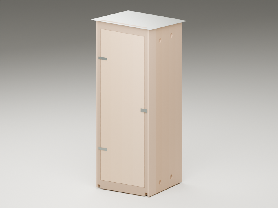
A compact timber enclosure with a sloping roof, boarded door and four removable shelves.
Default dimensions are shown below. Enable JavaScript to edit dimensions and inspect the 3D model.
Dimensions
- width
- 654 mm
- depth
- 654 mm
- front Height
- 1,829 mm
- rear Height
- 1,753 mm
- frame Section
- 38 mm, 38 mm
- board Thickness
- 19 mm
- board Coverage
- 131 mm
- brace Section
- 38 mm, 89 mm
- door Gap
- 3 mm
- roof Overhang
- 35 mm
- roof Thickness
- 2 mm
- shelf Clearance
- 3 mm
- rack Angle Stock Length
- 2,400 mm
- rack Support Section
- 38 mm, 38 mm
- rack Levels
- 457 mm, 813 mm, 1,168 mm, 1,524 mm
- upper Vent Diameter
- 51 mm
- lower Vent Diameter
- 51 mm
- board Stock Length
- 2,400 mm
- frame Stock Length
- 2,400 mm
- brace Stock Length
- 2,400 mm
- rack Stock Length
- 2,400 mm
- sheet Stock
- 1,219 mm, 2,438 mm
- kerf
- 3 mm
Shopping list
Quantities follow the dimensions above and have not been checked against a built example.
| Quantity | Item | Note |
|---|---|---|
| Timber | ||
| 11 2400 mm lengths | untreated timber38 mm × 38 mm section29 cuts · 4,631 mm offcut in total · 5 for frame, 2 for door batten, 2 for rack, 2 for rack backing | First-fit estimate with the entered saw kerf. Check grain and defects before cutting. |
| 1 2400 mm length | untreated timber38 mm × 89 mm section2 cuts · 1,315 mm offcut in total | |
| 20 2400 mm lengths | untreated tongue-and-groove pine19 mm × 131 mm section20 cuts · 12,991 mm offcut in total | |
| Metal lengths | ||
| 4 2400 mm lengths | steel angle2 mm × 12 mm section16 cuts · 988 mm offcut in total | First-fit estimate with the entered saw kerf; the section and material are proposed, not a listed product. |
| Sheet | ||
| 4 pieces to cut | expanded steel4 at 534 mm × 531 mmabout 1.13 m² of finished pieces, before overlaps and offcuts | The model gives finished sizes only; stock size and purchase quantity are not specified. |
| 1 piece to cut | non-galvanized sheet steel1 at 724 mm × 724 mmabout 0.52 m² of finished pieces, before overlaps and offcuts | |
| Mesh and screen | ||
| 8 pieces to cut | screen mesh8 at 76 mm × 76 mmabout 0.05 m² of finished pieces, before overlaps and offcuts | The model gives finished sizes only; stock size and purchase quantity are not specified. |
| Fixings and hardware | ||
| 2 pieces | four-inch strap hingesteel hardwaremodelled at 102 mm × 3 mm × 25 mm | A position marker in the model; the product, size and rating are not specified. |
| 1 piece | haspsteel hardwaremodelled at 80 mm × 5 mm × 35 mm | |
Cutting plan
Stock allocation uses the model’s kerf rule and the default stock lengths. No piece is spliced to fit.
board 1board
2,400 mm- 1,829 mm
Offcut 568 mm
board 2board
2,400 mm- 1,829 mm
Offcut 568 mm
board 3board
2,400 mm- 1,814 mm
Offcut 583 mm
board 4board
2,400 mm- 1,814 mm
Offcut 583 mm
board 5board
2,400 mm- 1,798 mm
Offcut 599 mm
board 6board
2,400 mm- 1,798 mm
Offcut 599 mm
board 7board
2,400 mm- 1,783 mm
Offcut 614 mm
board 8board
2,400 mm- 1,783 mm
Offcut 614 mm
board 9board
2,400 mm- 1,768 mm
Offcut 629 mm
board 10board
2,400 mm- 1,768 mm
Offcut 629 mm
board 11board
2,400 mm- 1,753 mm
Offcut 644 mm
board 12board
2,400 mm- 1,753 mm
Offcut 644 mm
board 13board
2,400 mm- 1,753 mm
Offcut 644 mm
board 14board
2,400 mm- 1,753 mm
Offcut 644 mm
board 15board
2,400 mm- 1,753 mm
Offcut 644 mm
board 16board
2,400 mm- 1,641 mm
Offcut 756 mm
board 17board
2,400 mm- 1,641 mm
Offcut 756 mm
board 18board
2,400 mm- 1,641 mm
Offcut 756 mm
board 19board
2,400 mm- 1,641 mm
Offcut 756 mm
board 20board
2,400 mm- 1,641 mm
Offcut 756 mm
frame 1frame
2,400 mm- 1,752 mm
- 635 mm
Offcut 7 mm
frame 2frame
2,400 mm- 1,752 mm
- 635 mm
Offcut 7 mm
frame 3frame
2,400 mm- 1,683 mm
- 644 mm
Offcut 67 mm
frame 4frame
2,400 mm- 1,683 mm
- 644 mm
Offcut 67 mm
frame 5frame
2,400 mm- 540 mm
- 540 mm
Offcut 1,315 mm
brace 1brace
2,400 mm- 540 mm
- 540 mm
Offcut 1,315 mm
door batten 1door batten
2,400 mm- 1,624 mm
- 458 mm
Offcut 313 mm
door batten 2door batten
2,400 mm- 458 mm
Offcut 1,939 mm
rack 1rack
2,400 mm- 540 mm
- 540 mm
- 540 mm
- 540 mm
Offcut 229 mm
rack 2rack
2,400 mm- 540 mm
- 540 mm
- 540 mm
- 540 mm
Offcut 229 mm
rack backing 1rack backing
2,400 mm- 540 mm
- 540 mm
- 540 mm
- 540 mm
Offcut 229 mm
rack backing 2rack backing
2,400 mm- 540 mm
- 540 mm
- 540 mm
- 540 mm
Offcut 229 mm
rack angle 1rack angle
2,400 mm- 537 mm
- 537 mm
- 537 mm
- 537 mm
Offcut 241 mm
rack angle 2rack angle
2,400 mm- 537 mm
- 537 mm
- 537 mm
- 537 mm
Offcut 241 mm
rack angle 3rack angle
2,400 mm- 534 mm
- 534 mm
- 534 mm
- 534 mm
Offcut 253 mm
rack angle 4rack angle
2,400 mm- 534 mm
- 534 mm
- 534 mm
- 534 mm
Offcut 253 mm
Cut list
| Part | Stock | Cut | Joint and angles |
|---|---|---|---|
| board | 1,829 mm × 131 mm | top slope cut; bottom square; edge profile retained where available Ends 90° / 83.355° | |
| board | 1,814 mm × 131 mm | top slope cut; bottom square; edge profile retained where available Ends 90° / 83.355° | |
| board | 1,798 mm × 131 mm | top slope cut; bottom square; edge profile retained where available Ends 90° / 83.355° | |
| board | 1,783 mm × 131 mm | top slope cut; bottom square; edge profile retained where available Ends 90° / 83.355° | |
| board | 1,768 mm × 131 mm | top slope cut; bottom square; edge profile retained where available Ends 90° / 83.355° | |
| frame | 635 mm × 38 mm | square butt; fastener layout unresolved Ends 90° / 90° | |
| frame | 1,752 mm × 38 mm | slope-cut post top bears on rail underside Ends 90° / 83.355° | |
| frame | 1,683 mm × 38 mm | slope-cut post top bears on rail underside Ends 90° / 83.355° | |
| frame | 644 mm × 38 mm | two slope-end cuts; bears on slope-cut posts; physical fit unresolved Ends 83.355° / 96.645° | |
| rack | 540 mm × 38 mm | square butt; fastener layout unresolved Ends 90° / 90° | |
| rack | 540 mm × 38 mm | square butt; fastener layout unresolved Ends 90° / 90° | |
| rack | 540 mm × 38 mm | square butt; fastener layout unresolved Ends 90° / 90° | |
| rack | 540 mm × 38 mm | square butt; fastener layout unresolved Ends 90° / 90° | |
| rack backing | 540 mm × 38 mm | wall/backing/cleat face stack; pilot from interior before shelves; fixing capacity unresolved Ends 90° / 90° | |
| rack backing | 540 mm × 38 mm | wall/backing/cleat face stack; pilot from interior before shelves; fixing capacity unresolved Ends 90° / 90° | |
| rack backing | 540 mm × 38 mm | wall/backing/cleat face stack; pilot from interior before shelves; fixing capacity unresolved Ends 90° / 90° | |
| rack backing | 540 mm × 38 mm | wall/backing/cleat face stack; pilot from interior before shelves; fixing capacity unresolved Ends 90° / 90° | |
| board | 1,829 mm × 131 mm | top slope cut; bottom square; edge profile retained where available Ends 90° / 83.355° | |
| board | 1,814 mm × 131 mm | top slope cut; bottom square; edge profile retained where available Ends 90° / 83.355° | |
| board | 1,798 mm × 131 mm | top slope cut; bottom square; edge profile retained where available Ends 90° / 83.355° | |
| board | 1,783 mm × 131 mm | top slope cut; bottom square; edge profile retained where available Ends 90° / 83.355° | |
| board | 1,768 mm × 131 mm | top slope cut; bottom square; edge profile retained where available Ends 90° / 83.355° | |
| frame | 635 mm × 38 mm | square butt; fastener layout unresolved Ends 90° / 90° | |
| frame | 1,752 mm × 38 mm | slope-cut post top bears on rail underside Ends 90° / 83.355° | |
| frame | 1,683 mm × 38 mm | slope-cut post top bears on rail underside Ends 90° / 83.355° | |
| frame | 644 mm × 38 mm | two slope-end cuts; bears on slope-cut posts; physical fit unresolved Ends 83.355° / 96.645° | |
| rack | 540 mm × 38 mm | square butt; fastener layout unresolved Ends 90° / 90° | |
| rack | 540 mm × 38 mm | square butt; fastener layout unresolved Ends 90° / 90° | |
| rack | 540 mm × 38 mm | square butt; fastener layout unresolved Ends 90° / 90° | |
| rack | 540 mm × 38 mm | square butt; fastener layout unresolved Ends 90° / 90° | |
| rack backing | 540 mm × 38 mm | wall/backing/cleat face stack; pilot from interior before shelves; fixing capacity unresolved Ends 90° / 90° | |
| rack backing | 540 mm × 38 mm | wall/backing/cleat face stack; pilot from interior before shelves; fixing capacity unresolved Ends 90° / 90° | |
| rack backing | 540 mm × 38 mm | wall/backing/cleat face stack; pilot from interior before shelves; fixing capacity unresolved Ends 90° / 90° | |
| rack backing | 540 mm × 38 mm | wall/backing/cleat face stack; pilot from interior before shelves; fixing capacity unresolved Ends 90° / 90° | |
| board | 1,753 mm × 131 mm | square butt; fastener layout unresolved Ends 90° / 90° | |
| board | 1,753 mm × 131 mm | square butt; fastener layout unresolved Ends 90° / 90° | |
| board | 1,753 mm × 131 mm | square butt; fastener layout unresolved Ends 90° / 90° | |
| board | 1,753 mm × 131 mm | square butt; fastener layout unresolved Ends 90° / 90° | |
| board | 1,753 mm × 93 mm | square butt; fastener layout unresolved Ends 90° / 90° | |
| board | 1,641 mm × 131 mm | square butt; fastener layout unresolved Ends 90° / 90° | |
| board | 1,641 mm × 131 mm | square butt; fastener layout unresolved Ends 90° / 90° | |
| board | 1,641 mm × 131 mm | square butt; fastener layout unresolved Ends 90° / 90° | |
| board | 1,641 mm × 131 mm | square butt; fastener layout unresolved Ends 90° / 90° | |
| board | 1,641 mm × 11 mm | square butt; fastener layout unresolved Ends 90° / 90° | |
| brace | 540 mm × 89 mm | proposed butt joint; source notch size unresolved Ends 90° / 90° | |
| frame | 540 mm × 38 mm | square butt; fastener layout unresolved Ends 90° / 90° | |
| brace | 540 mm × 89 mm | proposed butt joint; source notch size unresolved Ends 90° / 90° | |
| frame | 540 mm × 38 mm | square butt; fastener layout unresolved Ends 90° / 90° | |
| door batten | 458 mm × 38 mm | square butt; fastener layout unresolved Ends 90° / 90° | |
| door batten | 458 mm × 38 mm | square butt; fastener layout unresolved Ends 90° / 90° | |
| door batten | 1,624 mm × 38 mm | horizontal clipped end faces seat between battens; listed length is full along-grain blank Ends 74.98144391979366° / 74.98144391979366° | |
| sheet | 729 mm × 724 mm | plumb sheet edges; full along-plane blank; fixing and gap spacers unresolved Ends 83.355° / 96.645° | |
| rack sheet | 534 mm × 531 mm | sheet bears on angle flanges; deburr and select compatible attachment Ends 90° / 90° | |
| rack angle | 534 mm × 12 mm | proposed 12x12x1.5 angle; mitred45-degree corners; two flange meshes represent one cut Ends 45° / 45° | |
| rack angle | 534 mm × 12 mm | proposed 12x12x1.5 angle; mitred45-degree corners; two flange meshes represent one cut Ends 45° / 45° | |
| rack angle | 537 mm × 12 mm | proposed 12x12x1.5 angle; mitred45-degree corners; two flange meshes represent one cut Ends 45° / 45° | |
| rack angle | 537 mm × 12 mm | proposed 12x12x1.5 angle; mitred45-degree corners; two flange meshes represent one cut Ends 45° / 45° | |
| rack sheet | 534 mm × 531 mm | sheet bears on angle flanges; deburr and select compatible attachment Ends 90° / 90° | |
| rack angle | 534 mm × 12 mm | proposed 12x12x1.5 angle; mitred45-degree corners; two flange meshes represent one cut Ends 45° / 45° | |
| rack angle | 534 mm × 12 mm | proposed 12x12x1.5 angle; mitred45-degree corners; two flange meshes represent one cut Ends 45° / 45° | |
| rack angle | 537 mm × 12 mm | proposed 12x12x1.5 angle; mitred45-degree corners; two flange meshes represent one cut Ends 45° / 45° | |
| rack angle | 537 mm × 12 mm | proposed 12x12x1.5 angle; mitred45-degree corners; two flange meshes represent one cut Ends 45° / 45° | |
| rack sheet | 534 mm × 531 mm | sheet bears on angle flanges; deburr and select compatible attachment Ends 90° / 90° | |
| rack angle | 534 mm × 12 mm | proposed 12x12x1.5 angle; mitred45-degree corners; two flange meshes represent one cut Ends 45° / 45° | |
| rack angle | 534 mm × 12 mm | proposed 12x12x1.5 angle; mitred45-degree corners; two flange meshes represent one cut Ends 45° / 45° | |
| rack angle | 537 mm × 12 mm | proposed 12x12x1.5 angle; mitred45-degree corners; two flange meshes represent one cut Ends 45° / 45° | |
| rack angle | 537 mm × 12 mm | proposed 12x12x1.5 angle; mitred45-degree corners; two flange meshes represent one cut Ends 45° / 45° | |
| rack sheet | 534 mm × 531 mm | sheet bears on angle flanges; deburr and select compatible attachment Ends 90° / 90° | |
| rack angle | 534 mm × 12 mm | proposed 12x12x1.5 angle; mitred45-degree corners; two flange meshes represent one cut Ends 45° / 45° | |
| rack angle | 534 mm × 12 mm | proposed 12x12x1.5 angle; mitred45-degree corners; two flange meshes represent one cut Ends 45° / 45° | |
| rack angle | 537 mm × 12 mm | proposed 12x12x1.5 angle; mitred45-degree corners; two flange meshes represent one cut Ends 45° / 45° | |
| rack angle | 537 mm × 12 mm | proposed 12x12x1.5 angle; mitred45-degree corners; two flange meshes represent one cut Ends 45° / 45° | |
| screen | 76 mm × 76 mm | cut screen patch; attachment pattern unresolved Ends 90° / 90° | |
| screen | 76 mm × 76 mm | cut screen patch; attachment pattern unresolved Ends 90° / 90° | |
| screen | 76 mm × 76 mm | cut screen patch; attachment pattern unresolved Ends 90° / 90° | |
| screen | 76 mm × 76 mm | cut screen patch; attachment pattern unresolved Ends 90° / 90° | |
| screen | 76 mm × 76 mm | cut screen patch; attachment pattern unresolved Ends 90° / 90° | |
| screen | 76 mm × 76 mm | cut screen patch; attachment pattern unresolved Ends 90° / 90° | |
| screen | 76 mm × 76 mm | cut screen patch; attachment pattern unresolved Ends 90° / 90° | |
| screen | 76 mm × 76 mm | cut screen patch; attachment pattern unresolved Ends 90° / 90° |
Openings and fitted details
- door
- left
- 60 mm
- bottom
- 92 mm
- width
- 534 mm
- height
- 1,641 mm
- gap
- 3 mm
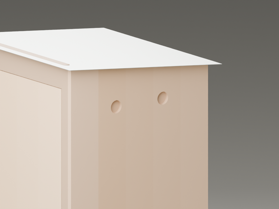
- vents
- id
- vent.left.upper.1
- side
- left
- center
- 0 mm, 216 mm, 1,648 mm
- diameter
- 51 mm
- status
- source-stated diameter and two upper holes per side; positions proposed
- id
- vent.left.lower.1
- side
- left
- center
- 0 mm, 216 mm, 105 mm
- diameter
- 51 mm
- status
- conditional source instruction for tight base; position proposed
- id
- vent.left.upper.2
- side
- left
- center
- 0 mm, 438 mm, 1,648 mm
- diameter
- 51 mm
- status
- source-stated diameter and two upper holes per side; positions proposed
- id
- vent.left.lower.2
- side
- left
- center
- 0 mm, 438 mm, 105 mm
- diameter
- 51 mm
- status
- conditional source instruction for tight base; position proposed
- id
- vent.right.upper.1
- side
- right
- center
- 654 mm, 216 mm, 1,648 mm
- diameter
- 51 mm
- status
- source-stated diameter and two upper holes per side; positions proposed
- id
- vent.right.lower.1
- side
- right
- center
- 654 mm, 216 mm, 105 mm
- diameter
- 51 mm
- status
- conditional source instruction for tight base; position proposed
- id
- vent.right.upper.2
- side
- right
- center
- 654 mm, 438 mm, 1,648 mm
- diameter
- 51 mm
- status
- source-stated diameter and two upper holes per side; positions proposed
- id
- vent.right.lower.2
- side
- right
- center
- 654 mm, 438 mm, 105 mm
- diameter
- 51 mm
- status
- conditional source instruction for tight base; position proposed
- roof gap
- 5 mm
- clear width
- 540 mm
- clear depth
- 540 mm
Parts
| Part | Material | Size | Basis |
|---|---|---|---|
| untreated tongue and groove pine | 19 mm × 131 mm × 1,829 mm | proposed adaptation | |
| untreated tongue and groove pine | 19 mm × 131 mm × 1,814 mm | proposed adaptation | |
| untreated tongue and groove pine | 19 mm × 131 mm × 1,798 mm | proposed adaptation | |
| untreated tongue and groove pine | 19 mm × 131 mm × 1,783 mm | proposed adaptation | |
| untreated tongue and groove pine | 19 mm × 131 mm × 1,768 mm | proposed adaptation | |
| untreated timber | 38 mm × 635 mm × 38 mm | proposed adaptation | |
| untreated timber | 38 mm × 38 mm × 1,752 mm | proposed adaptation | |
| untreated timber | 38 mm × 38 mm × 1,683 mm | proposed adaptation | |
| untreated timber | 38 mm × 635 mm × 186 mm | proposed adaptation | |
| untreated timber | 38 mm × 540 mm × 38 mm | proposed adaptation | |
| untreated timber | 38 mm × 540 mm × 38 mm | proposed adaptation | |
| untreated timber | 38 mm × 540 mm × 38 mm | proposed adaptation | |
| untreated timber | 38 mm × 540 mm × 38 mm | proposed adaptation | |
| untreated timber | 38 mm × 540 mm × 38 mm | proposed adaptation | |
| untreated timber | 38 mm × 540 mm × 38 mm | proposed adaptation | |
| untreated timber | 38 mm × 540 mm × 38 mm | proposed adaptation | |
| untreated timber | 38 mm × 540 mm × 38 mm | proposed adaptation | |
| untreated tongue and groove pine | 19 mm × 131 mm × 1,829 mm | proposed adaptation | |
| untreated tongue and groove pine | 19 mm × 131 mm × 1,814 mm | proposed adaptation | |
| untreated tongue and groove pine | 19 mm × 131 mm × 1,798 mm | proposed adaptation | |
| untreated tongue and groove pine | 19 mm × 131 mm × 1,783 mm | proposed adaptation | |
| untreated tongue and groove pine | 19 mm × 131 mm × 1,768 mm | proposed adaptation | |
| untreated timber | 38 mm × 635 mm × 38 mm | proposed adaptation | |
| untreated timber | 38 mm × 38 mm × 1,752 mm | proposed adaptation | |
| untreated timber | 38 mm × 38 mm × 1,683 mm | proposed adaptation | |
| untreated timber | 38 mm × 635 mm × 186 mm | proposed adaptation | |
| untreated timber | 38 mm × 540 mm × 38 mm | proposed adaptation | |
| untreated timber | 38 mm × 540 mm × 38 mm | proposed adaptation | |
| untreated timber | 38 mm × 540 mm × 38 mm | proposed adaptation | |
| untreated timber | 38 mm × 540 mm × 38 mm | proposed adaptation | |
| untreated timber | 38 mm × 540 mm × 38 mm | proposed adaptation | |
| untreated timber | 38 mm × 540 mm × 38 mm | proposed adaptation | |
| untreated timber | 38 mm × 540 mm × 38 mm | proposed adaptation | |
| untreated timber | 38 mm × 540 mm × 38 mm | proposed adaptation | |
| untreated tongue and groove pine | 131 mm × 19 mm × 1,753 mm | proposed adaptation | |
| untreated tongue and groove pine | 131 mm × 19 mm × 1,753 mm | proposed adaptation | |
| untreated tongue and groove pine | 131 mm × 19 mm × 1,753 mm | proposed adaptation | |
| untreated tongue and groove pine | 131 mm × 19 mm × 1,753 mm | proposed adaptation | |
| untreated tongue and groove pine | 93 mm × 19 mm × 1,753 mm | proposed adaptation | |
| untreated tongue and groove pine | 131 mm × 19 mm × 1,641 mm | proposed adaptation | |
| untreated tongue and groove pine | 131 mm × 19 mm × 1,641 mm | proposed adaptation | |
| untreated tongue and groove pine | 131 mm × 19 mm × 1,641 mm | proposed adaptation | |
| untreated tongue and groove pine | 131 mm × 19 mm × 1,641 mm | proposed adaptation | |
| untreated tongue and groove pine | 11 mm × 19 mm × 1,641 mm | proposed adaptation | |
| untreated timber | 540 mm × 38 mm × 89 mm | proposed adaptation | |
| untreated timber | 540 mm × 38 mm × 38 mm | proposed adaptation | |
| untreated timber | 540 mm × 38 mm × 89 mm | proposed adaptation | |
| untreated timber | 540 mm × 38 mm × 38 mm | proposed adaptation | |
| untreated timber | 458 mm × 38 mm × 38 mm | proposed adaptation | |
| untreated timber | 458 mm × 38 mm × 38 mm | proposed adaptation | |
| untreated timber | 458 mm × 38 mm × 1,558 mm | proposed adaptation | |
| non galvanized sheet steel | 724 mm × 724 mm × 170 mm | proposed adaptation | |
| expanded steel | 531 mm × 534 mm × 2 mm | proposed adaptation | |
| steel angle | 534 mm × 12 mm × 2 mm | proposed adaptation | |
| steel angle | 534 mm × 2 mm × 11 mm | proposed adaptation | |
| steel angle | 534 mm × 12 mm × 2 mm | proposed adaptation | |
| steel angle | 534 mm × 2 mm × 11 mm | proposed adaptation | |
| steel angle | 12 mm × 537 mm × 2 mm | proposed adaptation | |
| steel angle | 2 mm × 537 mm × 11 mm | proposed adaptation | |
| steel angle | 12 mm × 537 mm × 2 mm | proposed adaptation | |
| steel angle | 2 mm × 537 mm × 11 mm | proposed adaptation | |
| expanded steel | 531 mm × 534 mm × 2 mm | proposed adaptation | |
| steel angle | 534 mm × 12 mm × 2 mm | proposed adaptation | |
| steel angle | 534 mm × 2 mm × 11 mm | proposed adaptation | |
| steel angle | 534 mm × 12 mm × 2 mm | proposed adaptation | |
| steel angle | 534 mm × 2 mm × 11 mm | proposed adaptation | |
| steel angle | 12 mm × 537 mm × 2 mm | proposed adaptation | |
| steel angle | 2 mm × 537 mm × 11 mm | proposed adaptation | |
| steel angle | 12 mm × 537 mm × 2 mm | proposed adaptation | |
| steel angle | 2 mm × 537 mm × 11 mm | proposed adaptation | |
| expanded steel | 531 mm × 534 mm × 2 mm | proposed adaptation | |
| steel angle | 534 mm × 12 mm × 2 mm | proposed adaptation | |
| steel angle | 534 mm × 2 mm × 11 mm | proposed adaptation | |
| steel angle | 534 mm × 12 mm × 2 mm | proposed adaptation | |
| steel angle | 534 mm × 2 mm × 11 mm | proposed adaptation | |
| steel angle | 12 mm × 537 mm × 2 mm | proposed adaptation | |
| steel angle | 2 mm × 537 mm × 11 mm | proposed adaptation | |
| steel angle | 12 mm × 537 mm × 2 mm | proposed adaptation | |
| steel angle | 2 mm × 537 mm × 11 mm | proposed adaptation | |
| expanded steel | 531 mm × 534 mm × 2 mm | proposed adaptation | |
| steel angle | 534 mm × 12 mm × 2 mm | proposed adaptation | |
| steel angle | 534 mm × 2 mm × 11 mm | proposed adaptation | |
| steel angle | 534 mm × 12 mm × 2 mm | proposed adaptation | |
| steel angle | 534 mm × 2 mm × 11 mm | proposed adaptation | |
| steel angle | 12 mm × 537 mm × 2 mm | proposed adaptation | |
| steel angle | 2 mm × 537 mm × 11 mm | proposed adaptation | |
| steel angle | 12 mm × 537 mm × 2 mm | proposed adaptation | |
| steel angle | 2 mm × 537 mm × 11 mm | proposed adaptation | |
| screen mesh | 1 mm × 76 mm × 76 mm | proposed adaptation | |
| screen mesh | 1 mm × 76 mm × 76 mm | proposed adaptation | |
| screen mesh | 1 mm × 76 mm × 76 mm | proposed adaptation | |
| screen mesh | 1 mm × 76 mm × 76 mm | proposed adaptation | |
| screen mesh | 1 mm × 76 mm × 76 mm | proposed adaptation | |
| screen mesh | 1 mm × 76 mm × 76 mm | proposed adaptation | |
| screen mesh | 1 mm × 76 mm × 76 mm | proposed adaptation | |
| screen mesh | 1 mm × 76 mm × 76 mm | proposed adaptation | |
| steel hardware | 102 mm × 3 mm × 25 mm | proposed adaptation | |
| steel hardware | 102 mm × 3 mm × 25 mm | proposed adaptation | |
| steel hardware | 80 mm × 5 mm × 35 mm | proposed adaptation |
Build steps and tools
Measure and lay out
Measure dressed frame section, board thickness and exposed tongue-and-groove coverage. Lay out both side slopes from the entered front and rear heights.
Tape measure, square, pencil, chalk line and clamps.
tape measuresquaremarking pencilchalk lineclampCut the panels and frame
Rip actual frame stock and cut the sloped side panels. Dry-fit the sloped post/rail contacts before fastening.
Table or hand rip saw for ripping; guided circular/track or hand saw for the long slope; mitre/chop saw for supported crosscuts. A mitre saw does not rip long boards.
table sawhand rip sawcircular sawhandsawmitre sawAssemble the enclosure and door
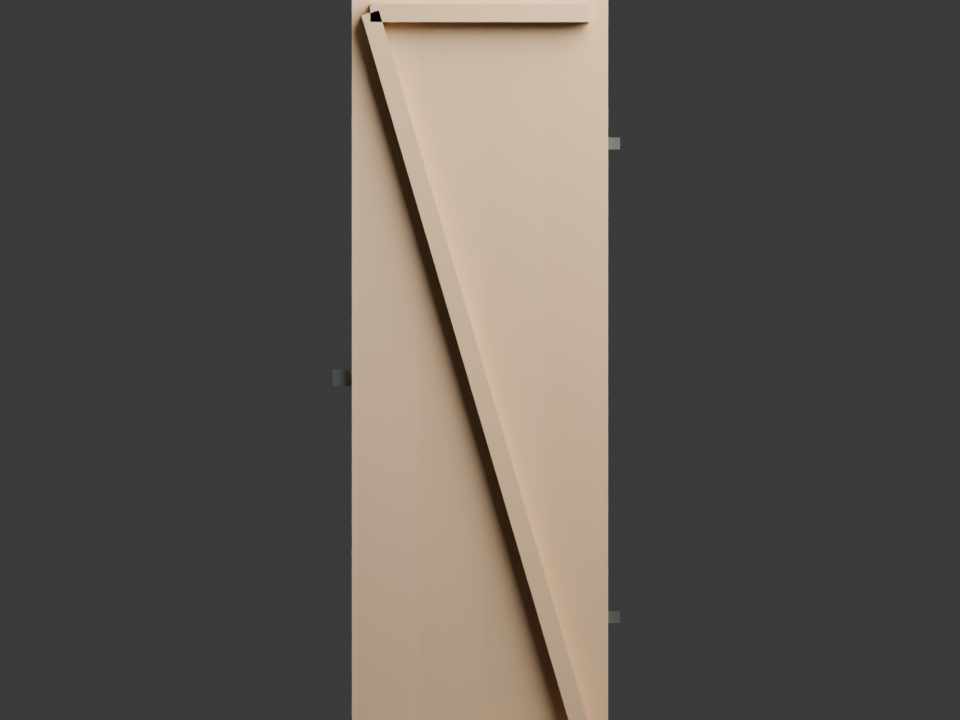
Test pilots and edge distances in offcuts. Assemble the side, back and front frames. Fit the Z-braced door using actual hinge and latch templates; check its full swing.
Drill/driver, pilot and countersink bits, screwdriver and clamps. An impact driver needs a tested screw/timber combination to avoid splitting.
drill driverdrill bitcountersink bitscrewdriverclampimpact driverFit shelves, vents and roof
Check support contact and shelf removal. Cut vents clear of the frame; fit a reviewed screen detail. Resolve roof drainage, spacers and sharp edges.
Rated metal shears or another tool suited to the actual sheet/mesh; jigsaw or suitable hole saw for vents. Staple gun is a candidate only after mesh/fastener testing.
shearsjigsawhole sawstaple gunReview before use
Test shelf loads, anchoring, joints, cleaning access and weathering. Resolve the fuel installation, fire separation and a selected food process before use.
Physical prototype and qualified structural/fire/process review remain outstanding.
Before you build
Door movement, joints, shelf loads, metal edges and screen fixing need physical review. Fire separation, fuel integration and a selected food process remain unvalidated.
- Door movement, joints, shelf loads, metal edges and screen fixing need physical review. Fire separation, fuel integration and a selected food process remain unvalidated.
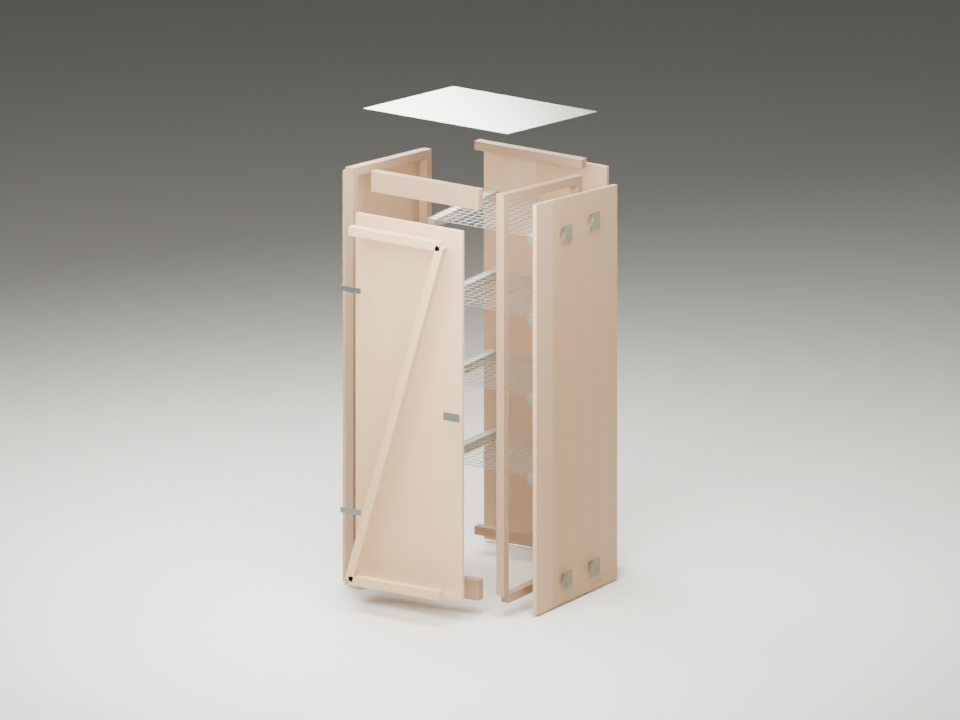
- Sloped boards, rails, roof and diagonal bracing follow the dimensional model. Screen and shelf surfaces are translucent envelopes; their wire geometry and fixing are unresolved. Hardware is a location marker.
What the 3D model leaves out
Sloped boards, rails, roof and diagonal bracing follow the dimensional model. Screen and shelf surfaces are translucent envelopes; their wire geometry and fixing are unresolved. Hardware is a location marker.
Taking the model apart separates parts for inspection; it is not an assembly order.
Dimension evidence and geometric checks
- publication
- UConn Extension EXT195, revised April 2026; original 2006
- url
- https://extension.uconn.edu/publication/build-your-own-smokehouse/
- appendix
- https://animalscience-cahnr.media.uconn.edu/wp-content/uploads/sites/3396/2022/06/building-a-smokehouse.pdf
- status
- pass
- part count
- 99
- cut count
- 80
- stock count
- 36
- unique ids
- Yes
- rack below roof
- Yes
- contact
- back rail between side frames
- Yes
- back wall between side walls
- Yes
- front braces between side frames
- Yes
- side posts bear on top rail without overlap
- Yes
- door symmetric gap
- Yes
- rack support bearing
- Yes
- vents clear side posts
- Yes
- vents below sloped top
- Yes
- lower vents above bottom frame
- Yes
- door clearance
- 3 mm
- limits
- Geometric contacts only; no physical fit, strength, hinge swing, thermal clearance, smoke distribution or food-process validation
Reference renders
Fixed views of the original proposal. They do not change with your dimensions.