Chorkor tray smoker, Ada-Foah
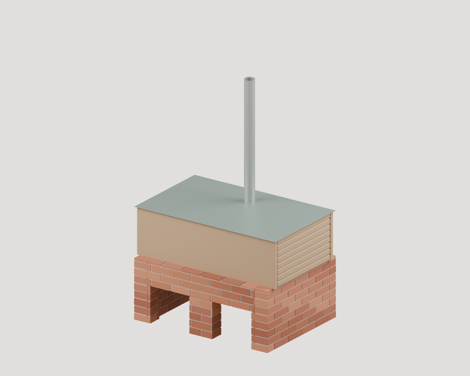
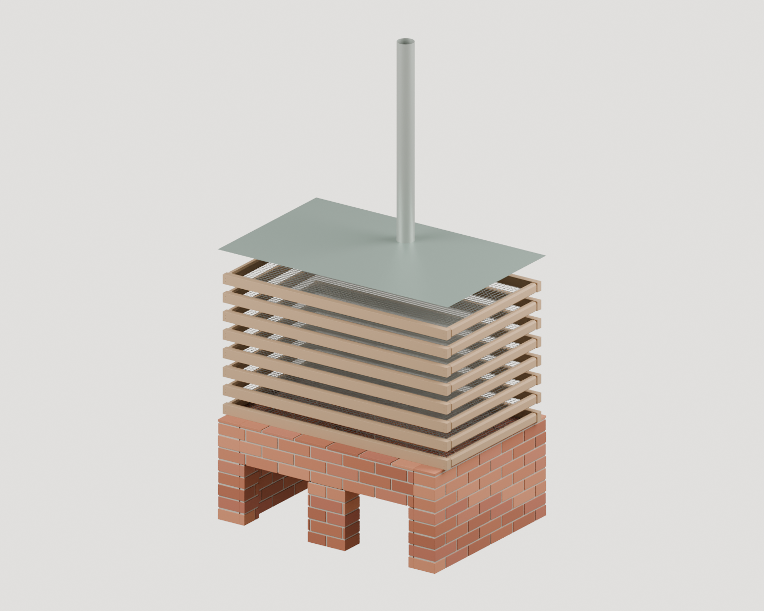
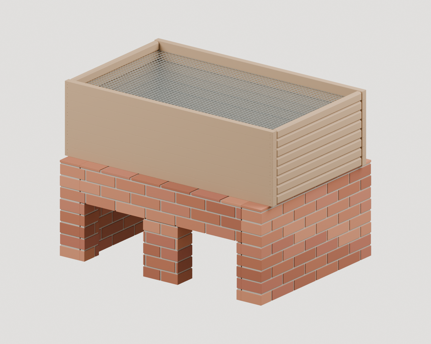
A clay combustion base with two fire openings, removable stacked mesh trays and a chimney cover.
Default dimensions are shown below. Enable JavaScript to edit dimensions and inspect the 3D model.
Dimensions
- tray Length
- 1560
- tray Width
- 950
- tray Height
- 60
- tray Count
- 8
- timber Width
- 40
- mesh Inset
- 20
- mesh Wire Diameter
- 2
- mesh Pitch
- 25
- mesh Sheet Width
- 1000
- base Length
- 1510
- base Width
- 1120
- base Height
- 620
- wall Thickness
- 150
- firepot Width
- 440
- firepot Height
- 380
- firepot Center Offset
- 350
- chimney Diameter
- 105
- chimney Length
- 1220
- cap Overhang
- 20
- cap Thickness
- 1
- stock Length
- 2400
- kerf
- 3
- staple Max Spacing
- 100
- screw Inset From End
- 20
- chimney Wall Thickness
- 2
Shopping list
Quantities follow the dimensions above and have not been checked against a built example.
| Quantity | Item | Note |
|---|---|---|
| Timber | ||
| 24 2400 mm lengths | timber40 mm × 60 mm section32 cuts · 18,624 mm offcut in total | First-fit estimate with the entered saw kerf. Check grain and defects before cutting. |
| Sheet | ||
| 1 piece | galvanized sheet cap1,600 mm × 990 mm | |
| Pipe and duct | ||
| 1 piece | galvanized chimney pipe105 mm diameter, 1,220 mm long | |
| Fixings and hardware | ||
| 416 pieces | mesh staples | Proposed maximum spacing; suitability requires prototype review. |
| 64 pieces | tray corner screws | Proposed count; length/grade require prototype review. |
| Other materials | ||
| geometric m³ (volume, not a purchase amount) | clay-sand0.383 geometric m³ | Finished geometric volume only; dry mix and shrinkage cannot be inferred. |
Cutting plan
Stock allocation uses the model’s kerf rule and the default stock lengths. No piece is spliced to fit.
B01timber
2,400 mm- 1,560 mm
Offcut 837 mm
B02timber
2,400 mm- 1,560 mm
Offcut 837 mm
B03timber
2,400 mm- 1,560 mm
Offcut 837 mm
B04timber
2,400 mm- 1,560 mm
Offcut 837 mm
B05timber
2,400 mm- 1,560 mm
Offcut 837 mm
B06timber
2,400 mm- 1,560 mm
Offcut 837 mm
B07timber
2,400 mm- 1,560 mm
Offcut 837 mm
B08timber
2,400 mm- 1,560 mm
Offcut 837 mm
B09timber
2,400 mm- 1,560 mm
Offcut 837 mm
B10timber
2,400 mm- 1,560 mm
Offcut 837 mm
B11timber
2,400 mm- 1,560 mm
Offcut 837 mm
B12timber
2,400 mm- 1,560 mm
Offcut 837 mm
B13timber
2,400 mm- 1,560 mm
Offcut 837 mm
B14timber
2,400 mm- 1,560 mm
Offcut 837 mm
B15timber
2,400 mm- 1,560 mm
Offcut 837 mm
B16timber
2,400 mm- 1,560 mm
Offcut 837 mm
B17timber
2,400 mm- 870 mm
- 870 mm
Offcut 654 mm
B18timber
2,400 mm- 870 mm
- 870 mm
Offcut 654 mm
B19timber
2,400 mm- 870 mm
- 870 mm
Offcut 654 mm
B20timber
2,400 mm- 870 mm
- 870 mm
Offcut 654 mm
B21timber
2,400 mm- 870 mm
- 870 mm
Offcut 654 mm
B22timber
2,400 mm- 870 mm
- 870 mm
Offcut 654 mm
B23timber
2,400 mm- 870 mm
- 870 mm
Offcut 654 mm
B24timber
2,400 mm- 870 mm
- 870 mm
Offcut 654 mm
Cut list
| Part | Stock | Cut | Joint and angles |
|---|---|---|---|
| timber | 1,560 mm | square crosscut; cut proposed inner underside mesh rebate; pilot two holes at each corner through side into end member Ends 90° / 90° | |
| timber | 1,560 mm | square crosscut; cut proposed inner underside mesh rebate; pilot two holes at each corner through side into end member Ends 90° / 90° | |
| timber | 870 mm | square crosscut; cut proposed inner underside mesh rebate and derived grip chamfer at 45° on upper outer edge, stopped one timber width before each butt end Ends 90° / 90° | |
| timber | 870 mm | square crosscut; cut proposed inner underside mesh rebate and derived grip chamfer at 45° on upper outer edge, stopped one timber width before each butt end Ends 90° / 90° | |
| mesh | 1,520 mm × 910 mm | shear blank; turn sharp wire ends into proposed underside rebate and staple flush | |
| timber | 1,560 mm | square crosscut; cut proposed inner underside mesh rebate; pilot two holes at each corner through side into end member Ends 90° / 90° | |
| timber | 1,560 mm | square crosscut; cut proposed inner underside mesh rebate; pilot two holes at each corner through side into end member Ends 90° / 90° | |
| timber | 870 mm | square crosscut; cut proposed inner underside mesh rebate and derived grip chamfer at 45° on upper outer edge, stopped one timber width before each butt end Ends 90° / 90° | |
| timber | 870 mm | square crosscut; cut proposed inner underside mesh rebate and derived grip chamfer at 45° on upper outer edge, stopped one timber width before each butt end Ends 90° / 90° | |
| mesh | 1,520 mm × 910 mm | shear blank; turn sharp wire ends into proposed underside rebate and staple flush | |
| timber | 1,560 mm | square crosscut; cut proposed inner underside mesh rebate; pilot two holes at each corner through side into end member Ends 90° / 90° | |
| timber | 1,560 mm | square crosscut; cut proposed inner underside mesh rebate; pilot two holes at each corner through side into end member Ends 90° / 90° | |
| timber | 870 mm | square crosscut; cut proposed inner underside mesh rebate and derived grip chamfer at 45° on upper outer edge, stopped one timber width before each butt end Ends 90° / 90° | |
| timber | 870 mm | square crosscut; cut proposed inner underside mesh rebate and derived grip chamfer at 45° on upper outer edge, stopped one timber width before each butt end Ends 90° / 90° | |
| mesh | 1,520 mm × 910 mm | shear blank; turn sharp wire ends into proposed underside rebate and staple flush | |
| timber | 1,560 mm | square crosscut; cut proposed inner underside mesh rebate; pilot two holes at each corner through side into end member Ends 90° / 90° | |
| timber | 1,560 mm | square crosscut; cut proposed inner underside mesh rebate; pilot two holes at each corner through side into end member Ends 90° / 90° | |
| timber | 870 mm | square crosscut; cut proposed inner underside mesh rebate and derived grip chamfer at 45° on upper outer edge, stopped one timber width before each butt end Ends 90° / 90° | |
| timber | 870 mm | square crosscut; cut proposed inner underside mesh rebate and derived grip chamfer at 45° on upper outer edge, stopped one timber width before each butt end Ends 90° / 90° | |
| mesh | 1,520 mm × 910 mm | shear blank; turn sharp wire ends into proposed underside rebate and staple flush | |
| timber | 1,560 mm | square crosscut; cut proposed inner underside mesh rebate; pilot two holes at each corner through side into end member Ends 90° / 90° | |
| timber | 1,560 mm | square crosscut; cut proposed inner underside mesh rebate; pilot two holes at each corner through side into end member Ends 90° / 90° | |
| timber | 870 mm | square crosscut; cut proposed inner underside mesh rebate and derived grip chamfer at 45° on upper outer edge, stopped one timber width before each butt end Ends 90° / 90° | |
| timber | 870 mm | square crosscut; cut proposed inner underside mesh rebate and derived grip chamfer at 45° on upper outer edge, stopped one timber width before each butt end Ends 90° / 90° | |
| mesh | 1,520 mm × 910 mm | shear blank; turn sharp wire ends into proposed underside rebate and staple flush | |
| timber | 1,560 mm | square crosscut; cut proposed inner underside mesh rebate; pilot two holes at each corner through side into end member Ends 90° / 90° | |
| timber | 1,560 mm | square crosscut; cut proposed inner underside mesh rebate; pilot two holes at each corner through side into end member Ends 90° / 90° | |
| timber | 870 mm | square crosscut; cut proposed inner underside mesh rebate and derived grip chamfer at 45° on upper outer edge, stopped one timber width before each butt end Ends 90° / 90° | |
| timber | 870 mm | square crosscut; cut proposed inner underside mesh rebate and derived grip chamfer at 45° on upper outer edge, stopped one timber width before each butt end Ends 90° / 90° | |
| mesh | 1,520 mm × 910 mm | shear blank; turn sharp wire ends into proposed underside rebate and staple flush | |
| timber | 1,560 mm | square crosscut; cut proposed inner underside mesh rebate; pilot two holes at each corner through side into end member Ends 90° / 90° | |
| timber | 1,560 mm | square crosscut; cut proposed inner underside mesh rebate; pilot two holes at each corner through side into end member Ends 90° / 90° | |
| timber | 870 mm | square crosscut; cut proposed inner underside mesh rebate and derived grip chamfer at 45° on upper outer edge, stopped one timber width before each butt end Ends 90° / 90° | |
| timber | 870 mm | square crosscut; cut proposed inner underside mesh rebate and derived grip chamfer at 45° on upper outer edge, stopped one timber width before each butt end Ends 90° / 90° | |
| mesh | 1,520 mm × 910 mm | shear blank; turn sharp wire ends into proposed underside rebate and staple flush | |
| timber | 1,560 mm | square crosscut; cut proposed inner underside mesh rebate; pilot two holes at each corner through side into end member Ends 90° / 90° | |
| timber | 1,560 mm | square crosscut; cut proposed inner underside mesh rebate; pilot two holes at each corner through side into end member Ends 90° / 90° | |
| timber | 870 mm | square crosscut; cut proposed inner underside mesh rebate and derived grip chamfer at 45° on upper outer edge, stopped one timber width before each butt end Ends 90° / 90° | |
| timber | 870 mm | square crosscut; cut proposed inner underside mesh rebate and derived grip chamfer at 45° on upper outer edge, stopped one timber width before each butt end Ends 90° / 90° | |
| mesh | 1,520 mm × 910 mm | shear blank; turn sharp wire ends into proposed underside rebate and staple flush | |
| galvanized sheet | 1,600 mm × 990 mm | shear rectangle and cut round chimney opening; edge treatment and attachment require review | |
| galvanized pipe | 1,220 mm | cut pipe and deburr; mounting detail requires review |
Openings and fitted details
- id
- firepot-left
- face
- front
- center
- -350 mm, -560 mm, 190 mm
- size
- 440 mm, 150 mm, 380 mm
- status
- proposed selection from conflicting source values
- id
- firepot-right
- face
- front
- center
- 350 mm, -560 mm, 190 mm
- size
- 440 mm, 150 mm, 380 mm
- status
- proposed selection from conflicting source values
- id
- cap-chimney-hole
- face
- cap
- center
- 0 mm, 238 mm, 1,101 mm
- diameter
- 101 mm
- status
- proposed outlet matches pipe bore; pipe wall bears on cap annulus
Parts
| Part | Material | Size | Basis |
|---|---|---|---|
| clay sand | 150 mm × 1,120 mm × 620 mm | proposed geometric adaptation | |
| clay sand | 150 mm × 1,120 mm × 620 mm | proposed geometric adaptation | |
| clay sand | 1,210 mm × 150 mm × 620 mm | proposed geometric adaptation | |
| clay sand | 35 mm × 150 mm × 380 mm | proposed geometric adaptation | |
| clay sand | 260 mm × 150 mm × 380 mm | proposed geometric adaptation | |
| clay sand | 35 mm × 150 mm × 380 mm | proposed geometric adaptation | |
| clay sand | 1,210 mm × 150 mm × 240 mm | proposed geometric adaptation | |
| timber | 1,560 mm × 40 mm × 60 mm | proposed joinery; source states outer tray size only | |
| timber | 1,560 mm × 40 mm × 60 mm | proposed joinery; source states outer tray size only | |
| timber | 40 mm × 870 mm × 60 mm | proposed joinery; source states outer tray size only | |
| timber | 40 mm × 870 mm × 60 mm | proposed joinery; source states outer tray size only | |
| mesh | 1,520 mm × 910 mm × 2 mm | proposed mesh specification in flush underside rebate with staple attachment | |
| timber | 1,560 mm × 40 mm × 60 mm | proposed joinery; source states outer tray size only | |
| timber | 1,560 mm × 40 mm × 60 mm | proposed joinery; source states outer tray size only | |
| timber | 40 mm × 870 mm × 60 mm | proposed joinery; source states outer tray size only | |
| timber | 40 mm × 870 mm × 60 mm | proposed joinery; source states outer tray size only | |
| mesh | 1,520 mm × 910 mm × 2 mm | proposed mesh specification in flush underside rebate with staple attachment | |
| timber | 1,560 mm × 40 mm × 60 mm | proposed joinery; source states outer tray size only | |
| timber | 1,560 mm × 40 mm × 60 mm | proposed joinery; source states outer tray size only | |
| timber | 40 mm × 870 mm × 60 mm | proposed joinery; source states outer tray size only | |
| timber | 40 mm × 870 mm × 60 mm | proposed joinery; source states outer tray size only | |
| mesh | 1,520 mm × 910 mm × 2 mm | proposed mesh specification in flush underside rebate with staple attachment | |
| timber | 1,560 mm × 40 mm × 60 mm | proposed joinery; source states outer tray size only | |
| timber | 1,560 mm × 40 mm × 60 mm | proposed joinery; source states outer tray size only | |
| timber | 40 mm × 870 mm × 60 mm | proposed joinery; source states outer tray size only | |
| timber | 40 mm × 870 mm × 60 mm | proposed joinery; source states outer tray size only | |
| mesh | 1,520 mm × 910 mm × 2 mm | proposed mesh specification in flush underside rebate with staple attachment | |
| timber | 1,560 mm × 40 mm × 60 mm | proposed joinery; source states outer tray size only | |
| timber | 1,560 mm × 40 mm × 60 mm | proposed joinery; source states outer tray size only | |
| timber | 40 mm × 870 mm × 60 mm | proposed joinery; source states outer tray size only | |
| timber | 40 mm × 870 mm × 60 mm | proposed joinery; source states outer tray size only | |
| mesh | 1,520 mm × 910 mm × 2 mm | proposed mesh specification in flush underside rebate with staple attachment | |
| timber | 1,560 mm × 40 mm × 60 mm | proposed joinery; source states outer tray size only | |
| timber | 1,560 mm × 40 mm × 60 mm | proposed joinery; source states outer tray size only | |
| timber | 40 mm × 870 mm × 60 mm | proposed joinery; source states outer tray size only | |
| timber | 40 mm × 870 mm × 60 mm | proposed joinery; source states outer tray size only | |
| mesh | 1,520 mm × 910 mm × 2 mm | proposed mesh specification in flush underside rebate with staple attachment | |
| timber | 1,560 mm × 40 mm × 60 mm | proposed joinery; source states outer tray size only | |
| timber | 1,560 mm × 40 mm × 60 mm | proposed joinery; source states outer tray size only | |
| timber | 40 mm × 870 mm × 60 mm | proposed joinery; source states outer tray size only | |
| timber | 40 mm × 870 mm × 60 mm | proposed joinery; source states outer tray size only | |
| mesh | 1,520 mm × 910 mm × 2 mm | proposed mesh specification in flush underside rebate with staple attachment | |
| timber | 1,560 mm × 40 mm × 60 mm | proposed joinery; source states outer tray size only | |
| timber | 1,560 mm × 40 mm × 60 mm | proposed joinery; source states outer tray size only | |
| timber | 40 mm × 870 mm × 60 mm | proposed joinery; source states outer tray size only | |
| timber | 40 mm × 870 mm × 60 mm | proposed joinery; source states outer tray size only | |
| mesh | 1,520 mm × 910 mm × 2 mm | proposed mesh specification in flush underside rebate with staple attachment | |
| galvanized sheet | 1,600 mm × 990 mm × 1 mm | proposed cap and outlet location | |
| galvanized pipe | 105 mm × 105 mm × 1,220 mm | source nominal diameter interpreted as outside and source length; wall and annular cap seat proposed; restraint and weld unresolved |
Build steps and tools
Resolve the source dimensions
Keep this Ada-Foah variant distinct from Otuam. Resolve the conflicting source fire-opening dimensions with site measurements.
Tape measure, square and level; the clay base is a geometric volume, not a coursing or shrinkage schedule.
tape measuresquareSet out the combustion base
Review foundations, clay/sand preparation, wall shrinkage and lintel support before constructing the base and two openings.
Masonry mixing and forming tools need local builder selection. No universal curing time or mix performance is established here.
Cut and dry-fit the trays
Use measured rail width and height. Crosscut the long and end rails, test corner pilots and review the proposed grip chamfer.
Hand crosscut or ryōba saw, mitre/chop saw for repeat lengths, clamps, square, drill/driver, pilot bit and screwdriver. Rip/table or guided circular saw only when stock needs ripping.
hand crosscut sawryoba sawmitre sawclampsquaredrill driverdrill bitscrewdriverhand rip sawtable sawcircular sawFit mesh and stack the trays
Trim each mesh blank, turn sharp wire ends under the frame and test staple retention. Check bearing, loaded lifting and stability of the full stack.
Wire cutters or rated metal shears and a staple gun suited to the chosen mesh/fastener. A knife is unsuitable for metal mesh.
wire cuttersshearsstaple gunFit the cover and chimney
Resolve cover edge treatment, chimney support and material suitability. Test cleaning access, heat exposure and the selected food process separately.
Sheet-metal tools and a suitable opening cutter; power tools must match the material. Fire and food-process validation remain outstanding.
shears
Before you build
The source gives conflicting fire-opening sizes. Clay shrinkage, lintel strength, loaded tray lifting, stack stability, mesh retention, metal suitability and fire/food-process performance need physical review.
- The source gives conflicting fire-opening sizes. Clay shrinkage, lintel strength, loaded tray lifting, stack stability, mesh retention, metal suitability and fire/food-process performance need physical review.
- Individual brick surfaces illustrate a proposed adaptation of the documented clay base. Course sizes and joints are visual details, excluded from the cut list; they are not a verified masonry plan. Mesh is a translucent envelope. Tray rebates and grip chamfers follow the model. Wire weaving and pilot holes are listed but omitted from the interactive mesh. The chimney wall thickness is a proposed value, not a source dimension.
- The report also prints 380 mm × 420 mm for the same Ada-Foah firepots; the opening selection requires measurement.
What the 3D model leaves out
Individual brick surfaces illustrate a proposed adaptation of the documented clay base. Course sizes and joints are visual details, excluded from the cut list; they are not a verified masonry plan. Mesh is a translucent envelope. Tray rebates and grip chamfers follow the model. Wire weaving and pilot holes are listed but omitted from the interactive mesh. The chimney wall thickness is a proposed value, not a source dimension.
Taking the model apart separates parts for inspection; it is not an assembly order.
Dimension evidence and geometric checks
- source tray outer
- 1,560 mm, 950 mm, 60 mm
- source tray count
- 8
- source base outer
- 1,510 mm, 1,120 mm, 620 mm
- source wall thickness
- 150 mm
- conflicting source fire openings
- 440 mm, 380 mm, 380 mm, 420 mm
- clay to sand volume ratio
- 4, 1
- source chimney diameter
- 105 mm
- source chimney length
- 1,220 mm
- id
- open-tray-frame
- pass
- Yes
- detail
- Positive aperture, actual section and a grip run clear of both butt ends
- id
- mesh-rebate
- pass
- Yes
- detail
- Underside rebate fits the actual timber section and leaves outer wood bearing
- id
- pipe-wall
- pass
- Yes
- detail
- Entered outside diameter retains a positive bore with the proposed wall thickness
- id
- open-mesh
- pass
- Yes
- detail
- Wire diameter must be smaller than pitch
- id
- pilot-hole-fit
- pass
- Yes
- detail
- Both proposed pilot holes fit the tray height
- id
- base-cavity
- pass
- Yes
- detail
- Wall thickness leaves a positive open chamber
- id
- two-firepots
- pass
- Yes
- detail
- Both proposed firepots fit below a continuous front lintel
- id
- base-side-contact
- pass
- Yes
- detail
- At least half of each long tray rail has wood-to-clay bearing outside the mesh rebate
- id
- tray-stack-contact
- pass
- Yes
- detail
- Tray frames meet face to face without an interlock
- id
- mesh-roll-width
- pass
- Yes
- detail
- Proposed mesh blank fits available roll width
- id
- sheet-cap-opening
- pass
- Yes
- detail
- Proposed chimney hole fits inside the cap
- id
- actual-lattice-aperture
- pass
- Yes
- detail
- Fitted bars retain a positive actual clear aperture in both axes
- id
- lattice-size
- pass
- Yes
- detail
- Export budget is 4096 bars across trays; this is a computational bound, not a construction rating
- id
- timber-stock-fit
- pass
- Yes
- detail
- Whole members fit without splice; end kerf consumes only available remainder
Reference renders
Fixed views of the original proposal. They do not change with your dimensions.