Waters–Bond remote-firebox smoker
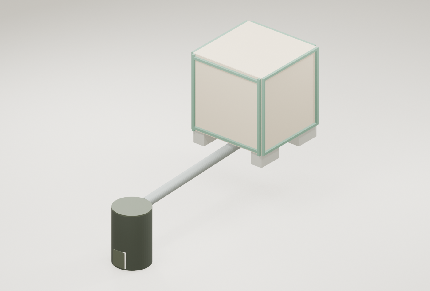
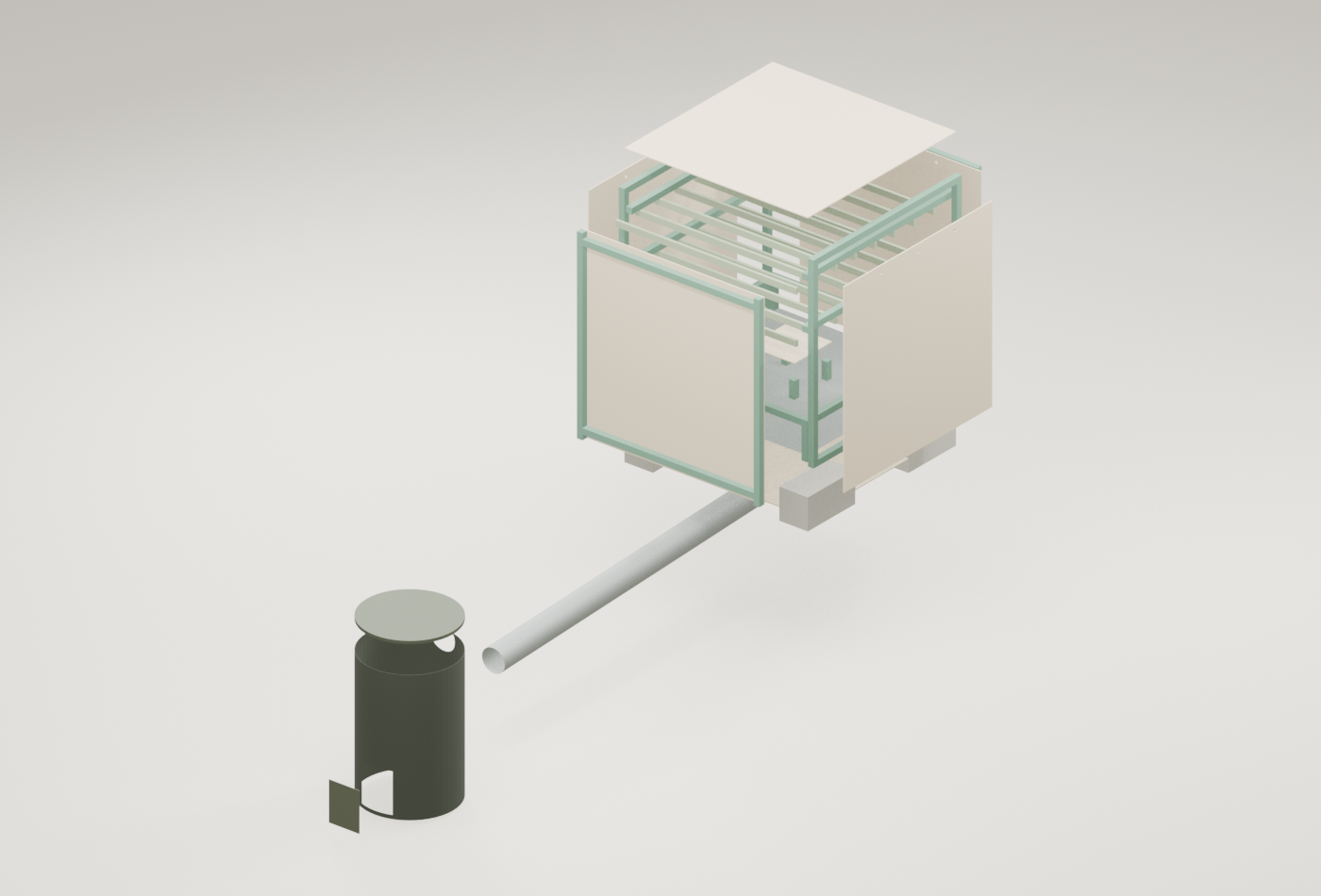
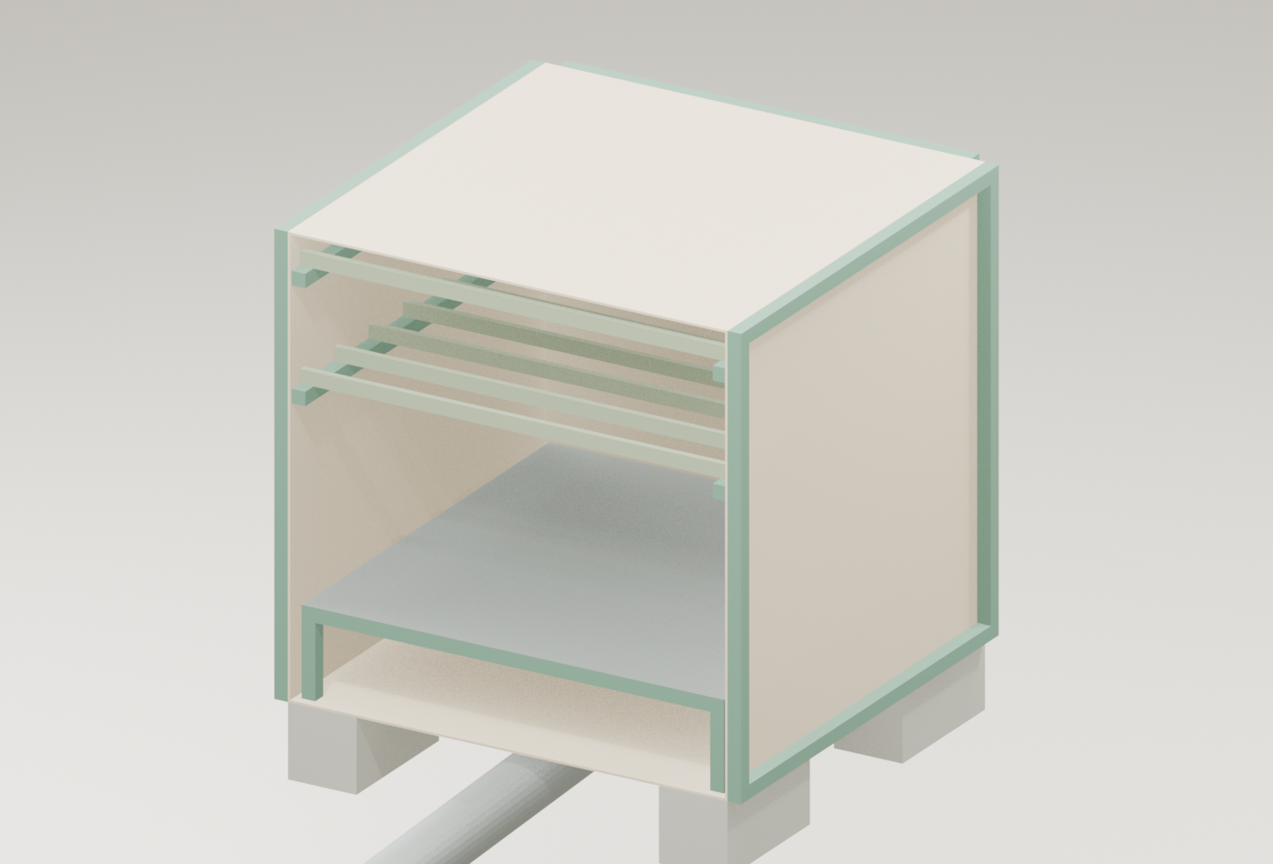
A plywood chamber, removable racks and tray, with a separate drum connected by a rising smoke duct.
Default dimensions are shown below. Enable JavaScript to edit dimensions and inspect the 3D model.
Dimensions
- width
- 1,216 mm
- depth
- 1,216 mm
- height
- 1,216 mm
- plywood
- 6 mm
- section
- 38 mm, 38 mm
- split Rack Thickness
- 18 mm
- board Length
- 2,400 mm
- sheet
- 1,219 mm, 2,438 mm
- kerf
- 3 mm
- door Gap
- 3 mm
- duct Diameter
- 152 mm
- duct Length
- 2,438 mm
- duct Wall
- 1 mm
- drum Diameter
- 572 mm
- drum Height
- 850 mm
- drum Wall
- 2 mm
- grade Drop
- 800 mm
- block Height
- 200 mm
- block Width
- 190 mm
- block Depth
- 390 mm
- post Pad Outset
- 75 mm
Shopping list
Quantities follow the dimensions above and have not been checked against a built example.
| Quantity | Item | Note |
|---|---|---|
| Timber | ||
| 20 boards | actual-section timbersource listed 38 | actual section and grade to measure |
| Sheet | ||
| 4 sheets | exterior plywoodsource listed 3 | calculated kerf-aware allocation; source quantity remains historical |
| Mesh and screen | ||
| 16 square feet | ½ in hardware cloth | source purchase quantity; edge fixing unspecified |
| Pipe and duct | ||
| 1 length | stovepipesource listed 8 | historical specification; present suitability unreviewed |
| 1 elbow | stovepipe elbow | bend and joint overlap unspecified |
| Fixings and hardware | ||
| 1 lb | 3-penny galvanized nails | source table; fastener suitability unreviewed |
| 1 lb | 8-penny finishing nails | |
| 5 hinges | brass butt hinges | two drum and three smoker hinges in article text |
| 1 handle | door handle | location proposed |
| 2 door sets | hook-and-eye closuressource listed 12 | two door sets in construction text; table lists 12 without positions |
| 240 hooks | small plated eye hooks | proposed count from actual centred rack layout; source fifteen per bar |
| 240 hooks | stainless-steel wire S-hooks | source 20 dozen; dimensions and wire gauge unverified |
| Sealants and coatings | ||
| coating, amount not specified | exterior wood sealer | source says two exterior coats; product and amount unverified |
| sealant, amount not specified | furnace cement | source uses at pipe/drum joint; current suitability unverified |
| Other materials | ||
| 1 drum | 55 gal removable-lid steel drum | material history and coating unknown |
| 4 blocks | concrete blocks | source floor blocks; dimensions and bearing proposed |
| 4 supports | separate outboard concrete post supports | proposed full post-sole support; material, footing, soil and strength unqualified |
Cutting plan
Stock allocation uses the model’s kerf rule and the default stock lengths. No piece is spliced to fit.
board 1board
2,400 mm- 1,216 mm
- 1,168 mm
Offcut 10 mm
board 2board
2,400 mm- 1,216 mm
- 1,168 mm
Offcut 10 mm
board 3board
2,400 mm- 1,216 mm
- 1,140 mm
Offcut 38 mm
board 4board
2,400 mm- 1,216 mm
- 1,140 mm
Offcut 38 mm
board 5board
2,400 mm- 1,210 mm
- 1,140 mm
Offcut 44 mm
board 6board
2,400 mm- 1,210 mm
- 1,140 mm
Offcut 44 mm
board 7board
2,400 mm- 1,203 mm
- 1,140 mm
Offcut 51 mm
board 8board
2,400 mm- 1,203 mm
- 1,140 mm
Offcut 51 mm
board 9board
2,400 mm- 1,203 mm
- 1,134 mm
Offcut 57 mm
board 10board
2,400 mm- 1,203 mm
- 1,134 mm
Offcut 57 mm
board 11board
2,400 mm- 1,092 mm
- 1,092 mm
- 203 mm
Offcut 3 mm
board 12board
2,400 mm- 203 mm
- 203 mm
- 203 mm
- 152 mm
- 152 mm
- 152 mm
- 152 mm
Offcut 1,160 mm
split board 1split board
2,400 mmTwo bars ripped from one board; their lengths overlap, so do not add them end to end.
- 1,199 mm
- 1,199 mm
Offcut 1,198 mm· rip kerf 3 mm
split board 2split board
2,400 mmTwo bars ripped from one board; their lengths overlap, so do not add them end to end.
- 1,199 mm
- 1,199 mm
Offcut 1,198 mm· rip kerf 3 mm
split board 3split board
2,400 mmTwo bars ripped from one board; their lengths overlap, so do not add them end to end.
- 1,199 mm
- 1,199 mm
Offcut 1,198 mm· rip kerf 3 mm
split board 4split board
2,400 mmTwo bars ripped from one board; their lengths overlap, so do not add them end to end.
- 1,199 mm
- 1,199 mm
Offcut 1,198 mm· rip kerf 3 mm
split board 5split board
2,400 mmTwo bars ripped from one board; their lengths overlap, so do not add them end to end.
- 1,199 mm
- 1,199 mm
Offcut 1,198 mm· rip kerf 3 mm
split board 6split board
2,400 mmTwo bars ripped from one board; their lengths overlap, so do not add them end to end.
- 1,199 mm
- 1,199 mm
Offcut 1,198 mm· rip kerf 3 mm
split board 7split board
2,400 mmTwo bars ripped from one board; their lengths overlap, so do not add them end to end.
- 1,199 mm
- 1,199 mm
Offcut 1,198 mm· rip kerf 3 mm
split board 8split board
2,400 mmTwo bars ripped from one board; their lengths overlap, so do not add them end to end.
- 1,199 mm
- 1,199 mm
Offcut 1,198 mm· rip kerf 3 mm
plywood 1
1,219 mm × 2,438 mm- 1,216 mm × 1,216 mm
- 1,216 mm × 1,216 mm
Placed one piece at a time with the entered kerf; not a nesting plan.
plywood 2
1,219 mm × 2,438 mm- 1,210 mm × 1,210 mm
- 1,216 mm × 1,203 mm
Placed one piece at a time with the entered kerf; not a nesting plan.
plywood 3
1,219 mm × 2,438 mm- 1,216 mm × 1,203 mm
- 1,203 mm × 1,203 mm
Placed one piece at a time with the entered kerf; not a nesting plan.
plywood 4
1,219 mm × 2,438 mm- 305 mm × 305 mm
Placed one piece at a time with the entered kerf; not a nesting plan.
Cut list
| Part | Stock | Cut | Joint and angles |
|---|---|---|---|
| plywood | 1,216 mm × 1,203 mm | Cut and joint details require physical verification. Saw angle from square 0° | |
| plywood | 1,216 mm × 1,203 mm | Cut and joint details require physical verification. Saw angle from square 0° | |
| plywood | 1,203 mm × 1,203 mm | Cut and joint details require physical verification. Saw angle from square 0° | |
| plywood | 1,216 mm × 1,216 mm | Cut and joint details require physical verification. Saw angle from square 0° | |
| plywood | 1,216 mm × 1,216 mm | Cut and joint details require physical verification. Saw angle from square 0° | |
| plywood | 1,210 mm × 1,210 mm | Cut and joint details require physical verification. Saw angle from square 0° | |
| board | 1,216 mm × 38 mm | Cut and joint details require physical verification. Saw angle from square 0° | |
| board | 1,216 mm × 38 mm | Cut and joint details require physical verification. Saw angle from square 0° | |
| board | 1,140 mm × 38 mm | Cut and joint details require physical verification. Saw angle from square 0° | |
| board | 1,140 mm × 38 mm | Cut and joint details require physical verification. Saw angle from square 0° | |
| board | 1,216 mm × 38 mm | Cut and joint details require physical verification. Saw angle from square 0° | |
| board | 1,216 mm × 38 mm | Cut and joint details require physical verification. Saw angle from square 0° | |
| board | 1,140 mm × 38 mm | Cut and joint details require physical verification. Saw angle from square 0° | |
| board | 1,140 mm × 38 mm | Cut and joint details require physical verification. Saw angle from square 0° | |
| board | 1,140 mm × 38 mm | Cut and joint details require physical verification. Saw angle from square 0° | |
| board | 1,140 mm × 38 mm | Cut and joint details require physical verification. Saw angle from square 0° | |
| board | 1,134 mm × 38 mm | Cut and joint details require physical verification. Saw angle from square 0° | |
| board | 1,134 mm × 38 mm | Cut and joint details require physical verification. Saw angle from square 0° | |
| board | 1,210 mm × 38 mm | Cut and joint details require physical verification. Saw angle from square 0° | |
| board | 1,210 mm × 38 mm | Cut and joint details require physical verification. Saw angle from square 0° | |
| board | 1,203 mm × 38 mm | Cut and joint details require physical verification. Saw angle from square 0° | |
| board | 1,203 mm × 38 mm | Cut and joint details require physical verification. Saw angle from square 0° | |
| split board | 1,199 mm × 38 mm | Cut and joint details require physical verification. Saw angle from square 0° | |
| split board | 1,199 mm × 38 mm | Cut and joint details require physical verification. Saw angle from square 0° | |
| split board | 1,199 mm × 38 mm | Cut and joint details require physical verification. Saw angle from square 0° | |
| split board | 1,199 mm × 38 mm | Cut and joint details require physical verification. Saw angle from square 0° | |
| split board | 1,199 mm × 38 mm | Cut and joint details require physical verification. Saw angle from square 0° | |
| split board | 1,199 mm × 38 mm | Cut and joint details require physical verification. Saw angle from square 0° | |
| split board | 1,199 mm × 38 mm | Cut and joint details require physical verification. Saw angle from square 0° | |
| split board | 1,199 mm × 38 mm | Cut and joint details require physical verification. Saw angle from square 0° | |
| board | 1,203 mm × 38 mm | Cut and joint details require physical verification. Saw angle from square 0° | |
| board | 1,203 mm × 38 mm | Cut and joint details require physical verification. Saw angle from square 0° | |
| split board | 1,199 mm × 38 mm | Cut and joint details require physical verification. Saw angle from square 0° | |
| split board | 1,199 mm × 38 mm | Cut and joint details require physical verification. Saw angle from square 0° | |
| split board | 1,199 mm × 38 mm | Cut and joint details require physical verification. Saw angle from square 0° | |
| split board | 1,199 mm × 38 mm | Cut and joint details require physical verification. Saw angle from square 0° | |
| split board | 1,199 mm × 38 mm | Cut and joint details require physical verification. Saw angle from square 0° | |
| split board | 1,199 mm × 38 mm | Cut and joint details require physical verification. Saw angle from square 0° | |
| split board | 1,199 mm × 38 mm | Cut and joint details require physical verification. Saw angle from square 0° | |
| split board | 1,199 mm × 38 mm | Cut and joint details require physical verification. Saw angle from square 0° | |
| plywood | 305 mm × 305 mm | Cut and joint details require physical verification. Saw angle from square 0° | |
| board | 152 mm × 38 mm | Cut and joint details require physical verification. Saw angle from square 0° | |
| board | 152 mm × 38 mm | Cut and joint details require physical verification. Saw angle from square 0° | |
| board | 152 mm × 38 mm | Cut and joint details require physical verification. Saw angle from square 0° | |
| board | 152 mm × 38 mm | Cut and joint details require physical verification. Saw angle from square 0° | |
| board | 203 mm × 38 mm | Cut and joint details require physical verification. Saw angle from square 0° | |
| board | 203 mm × 38 mm | Cut and joint details require physical verification. Saw angle from square 0° | |
| board | 203 mm × 38 mm | Cut and joint details require physical verification. Saw angle from square 0° | |
| board | 203 mm × 38 mm | Cut and joint details require physical verification. Saw angle from square 0° | |
| board | 1,168 mm × 38 mm | Cut and joint details require physical verification. Saw angle from square 0° | |
| board | 1,168 mm × 38 mm | Cut and joint details require physical verification. Saw angle from square 0° | |
| board | 1,092 mm × 38 mm | Cut and joint details require physical verification. Saw angle from square 0° | |
| board | 1,092 mm × 38 mm | Cut and joint details require physical verification. Saw angle from square 0° | |
| mesh roll | 1,168 mm × 1,168 mm | Cut and joint details require physical verification. Saw angle from square 0° | |
| 6 in galvanized stovepipe | 2,438 mm × 152 mm | Cut and joint details require physical verification. |
Openings and fitted details
- id
- chamber.door.opening
- type
- rectangle
- width
- 1,203 mm
- height
- 1,203 mm
- position
- 6 mm, 0 mm, 206 mm
- status
- derived
- id
- chamber.bottom.inlet
- type
- circle
- diameter
- 152 mm
- centre
- 608 mm, 608 mm, 206 mm
- status
- source diameter; centre from bottom-centre text
- id
- exhaust.left.1
- type
- circle
- diameter
- 19 mm
- centre
- 6 mm, 304 mm, 1,365 mm
- status
- source fig. 1 states 3/4 in exhaust holes; 3-per-face layout proposed
- id
- exhaust.left.2
- type
- circle
- diameter
- 19 mm
- centre
- 6 mm, 608 mm, 1,365 mm
- status
- source fig. 1 states 3/4 in exhaust holes; 3-per-face layout proposed
- id
- exhaust.left.3
- type
- circle
- diameter
- 19 mm
- centre
- 6 mm, 912 mm, 1,365 mm
- status
- source fig. 1 states 3/4 in exhaust holes; 3-per-face layout proposed
- id
- exhaust.right.1
- type
- circle
- diameter
- 19 mm
- centre
- 1,210 mm, 304 mm, 1,365 mm
- status
- source fig. 1 states 3/4 in exhaust holes; 3-per-face layout proposed
- id
- exhaust.right.2
- type
- circle
- diameter
- 19 mm
- centre
- 1,210 mm, 608 mm, 1,365 mm
- status
- source fig. 1 states 3/4 in exhaust holes; 3-per-face layout proposed
- id
- exhaust.right.3
- type
- circle
- diameter
- 19 mm
- centre
- 1,210 mm, 912 mm, 1,365 mm
- status
- source fig. 1 states 3/4 in exhaust holes; 3-per-face layout proposed
- id
- exhaust.back.1
- type
- circle
- diameter
- 19 mm
- centre
- 304 mm, 1,210 mm, 1,365 mm
- status
- source fig. 1 states 3/4 in exhaust holes; 3-per-face layout proposed
- id
- exhaust.back.2
- type
- circle
- diameter
- 19 mm
- centre
- 608 mm, 1,210 mm, 1,365 mm
- status
- source fig. 1 states 3/4 in exhaust holes; 3-per-face layout proposed
- id
- exhaust.back.3
- type
- circle
- diameter
- 19 mm
- centre
- 912 mm, 1,210 mm, 1,365 mm
- status
- source fig. 1 states 3/4 in exhaust holes; 3-per-face layout proposed
- id
- exhaust.door.1
- type
- circle
- diameter
- 19 mm
- centre
- 304 mm, 0 mm, 1,365 mm
- status
- source fig. 1 states 3/4 in exhaust holes; 3-per-face layout proposed
- id
- exhaust.door.2
- type
- circle
- diameter
- 19 mm
- centre
- 608 mm, 0 mm, 1,365 mm
- status
- source fig. 1 states 3/4 in exhaust holes; 3-per-face layout proposed
- id
- exhaust.door.3
- type
- circle
- diameter
- 19 mm
- centre
- 912 mm, 0 mm, 1,365 mm
- status
- source fig. 1 states 3/4 in exhaust holes; 3-per-face layout proposed
- id
- firebox.door
- type
- rectangle
- width
- 203 mm
- height
- 254 mm
- centre
- 608 mm, -2,398 mm, -648 mm
- status
- source size; lower-rim offset proposed
- id
- firebox.outlet
- type
- circle
- diameter
- 152 mm
- centre
- 608 mm, -1,826 mm, -36 mm
- status
- source diameter; near-top placement proposed
Parts
| Part | Material | Size | Basis |
|---|---|---|---|
| exterior plywood | 6 mm × 1,216 mm × 1,203 mm | derived from source envelope | |
| exterior plywood | 6 mm × 1,216 mm × 1,203 mm | derived from source envelope | |
| exterior plywood | 1,203 mm × 6 mm × 1,203 mm | derived from source envelope | |
| exterior plywood | 1,216 mm × 1,216 mm × 6 mm | derived from source envelope | |
| exterior plywood | 1,216 mm × 1,216 mm × 6 mm | derived from source envelope | |
| exterior plywood | 1,210 mm × 6 mm × 1,210 mm | derived from source envelope | |
| dressed timber | 38 mm × 38 mm × 1,216 mm | proposed section over source nominal 2×2 | |
| dressed timber | 38 mm × 38 mm × 1,216 mm | proposed section over source nominal 2×2 | |
| dressed timber | 38 mm × 1,140 mm × 38 mm | proposed section over source nominal 2×2 | |
| dressed timber | 38 mm × 1,140 mm × 38 mm | proposed section over source nominal 2×2 | |
| dressed timber | 38 mm × 38 mm × 1,216 mm | proposed section over source nominal 2×2 | |
| dressed timber | 38 mm × 38 mm × 1,216 mm | proposed section over source nominal 2×2 | |
| dressed timber | 38 mm × 1,140 mm × 38 mm | proposed section over source nominal 2×2 | |
| dressed timber | 38 mm × 1,140 mm × 38 mm | proposed section over source nominal 2×2 | |
| dressed timber | 1,140 mm × 38 mm × 38 mm | proposed section over source nominal 2×2 | |
| dressed timber | 1,140 mm × 38 mm × 38 mm | proposed section over source nominal 2×2 | |
| dressed timber | 1,134 mm × 38 mm × 38 mm | proposed section over source nominal 2×2 | |
| dressed timber | 1,134 mm × 38 mm × 38 mm | proposed section over source nominal 2×2 | |
| dressed timber | 38 mm × 38 mm × 1,210 mm | proposed section over source nominal 2×2 | |
| dressed timber | 38 mm × 38 mm × 1,210 mm | proposed section over source nominal 2×2 | |
| dressed timber | 38 mm × 1,203 mm × 38 mm | proposed section over source nominal 2×2 | |
| dressed timber | 38 mm × 1,203 mm × 38 mm | proposed section over source nominal 2×2 | |
| split dressed timber | 1,199 mm × 18 mm × 38 mm | adapted from source split rack bars | |
| split dressed timber | 1,199 mm × 18 mm × 38 mm | adapted from source split rack bars | |
| split dressed timber | 1,199 mm × 18 mm × 38 mm | adapted from source split rack bars | |
| split dressed timber | 1,199 mm × 18 mm × 38 mm | adapted from source split rack bars | |
| split dressed timber | 1,199 mm × 18 mm × 38 mm | adapted from source split rack bars | |
| split dressed timber | 1,199 mm × 18 mm × 38 mm | adapted from source split rack bars | |
| split dressed timber | 1,199 mm × 18 mm × 38 mm | adapted from source split rack bars | |
| split dressed timber | 1,199 mm × 18 mm × 38 mm | adapted from source split rack bars | |
| dressed timber | 38 mm × 1,203 mm × 38 mm | proposed section over source nominal 2×2 | |
| dressed timber | 38 mm × 1,203 mm × 38 mm | proposed section over source nominal 2×2 | |
| split dressed timber | 1,199 mm × 18 mm × 38 mm | adapted from source split rack bars | |
| split dressed timber | 1,199 mm × 18 mm × 38 mm | adapted from source split rack bars | |
| split dressed timber | 1,199 mm × 18 mm × 38 mm | adapted from source split rack bars | |
| split dressed timber | 1,199 mm × 18 mm × 38 mm | adapted from source split rack bars | |
| split dressed timber | 1,199 mm × 18 mm × 38 mm | adapted from source split rack bars | |
| split dressed timber | 1,199 mm × 18 mm × 38 mm | adapted from source split rack bars | |
| split dressed timber | 1,199 mm × 18 mm × 38 mm | adapted from source split rack bars | |
| split dressed timber | 1,199 mm × 18 mm × 38 mm | adapted from source split rack bars | |
| exterior plywood | 305 mm × 305 mm × 6 mm | source 12 in square, 1/4 in plywood | |
| dressed timber | 38 mm × 38 mm × 152 mm | source 6 in length; section adapted | |
| dressed timber | 38 mm × 38 mm × 152 mm | source 6 in length; section adapted | |
| dressed timber | 38 mm × 38 mm × 152 mm | source 6 in length; section adapted | |
| dressed timber | 38 mm × 38 mm × 152 mm | source 6 in length; section adapted | |
| dressed timber | 38 mm × 38 mm × 203 mm | source 8 in length; support footprint follows adapted tray corners | |
| dressed timber | 38 mm × 38 mm × 203 mm | source 8 in length; support footprint follows adapted tray corners | |
| dressed timber | 38 mm × 38 mm × 203 mm | source 8 in length; support footprint follows adapted tray corners | |
| dressed timber | 38 mm × 38 mm × 203 mm | source 8 in length; support footprint follows adapted tray corners | |
| dressed timber | 1,168 mm × 38 mm × 38 mm | proposed section over source nominal 2×2 | |
| dressed timber | 1,168 mm × 38 mm × 38 mm | proposed section over source nominal 2×2 | |
| dressed timber | 38 mm × 1,092 mm × 38 mm | proposed section over source nominal 2×2 | |
| dressed timber | 38 mm × 1,092 mm × 38 mm | proposed section over source nominal 2×2 | |
| 1/2 in hardware cloth | 1,168 mm × 1,168 mm × 1 mm | source 4 ft square cloth; trimmed to proposed tray fit | |
| steel drum | 572 mm × 572 mm × 850 mm | source 55 gal capacity; diameter and height proposed | |
| steel drum lid | 572 mm × 572 mm × 20 mm | source removable clamp on lid; lid depth proposed | |
| steel drum cutout | 203 mm × 3 mm × 254 mm | source 8 × 10 in cutout reused; flat rendering and lower rim offset proposed | |
| galvanized stovepipe | 152 mm × 2,443 mm × 302 mm | source 6 in nominal duct and 8 ft pipe; placed on proposed rise | |
| galvanized stovepipe | 152 mm × 152 mm × 143 mm | source 6 in elbow and 2 in projection; vertical upstand substitutes for unknown bend | |
| concrete block | 190 mm × 390 mm × 200 mm | source four blocks; size and orientation proposed | |
| concrete block | 190 mm × 390 mm × 200 mm | source four blocks; size and orientation proposed | |
| concrete block | 190 mm × 390 mm × 200 mm | source four blocks; size and orientation proposed | |
| concrete block | 190 mm × 390 mm × 200 mm | source four blocks; size and orientation proposed | |
| concrete block | 113 mm × 188 mm × 200 mm | proposed separate outboard support for full external post sole; foundation and material unqualified | |
| concrete block | 113 mm × 188 mm × 200 mm | proposed separate outboard support for full external post sole; foundation and material unqualified | |
| concrete block | 113 mm × 188 mm × 200 mm | proposed separate outboard support for full external post sole; foundation and material unqualified | |
| concrete block | 113 mm × 188 mm × 200 mm | proposed separate outboard support for full external post sole; foundation and material unqualified |
Build steps and tools
Review the site and actual materials
Survey the lower-grade firebox placement, bearing and separation. Measure stock and review the recalculated sheet and timber allocation.
The entered grade and pipe clearance are drawing dimensions, not approved fire clearances.
Fit chamber, door and racks
Assemble panels and external framing. Dry-fit door swing and exhaust placement. Rip and end-seat rack bars, then check removal and hook layout.
Use the operation-specific tool list below; actual fasteners and rack loads remain unresolved.
Fit the baffle and catch tray
Check baffle leg contact, tray corner bearing, mesh edge treatment and removal for cleaning.
Test the supports with the intended load; geometric bearing does not establish strength.
Dry-fit the drum and smoke path
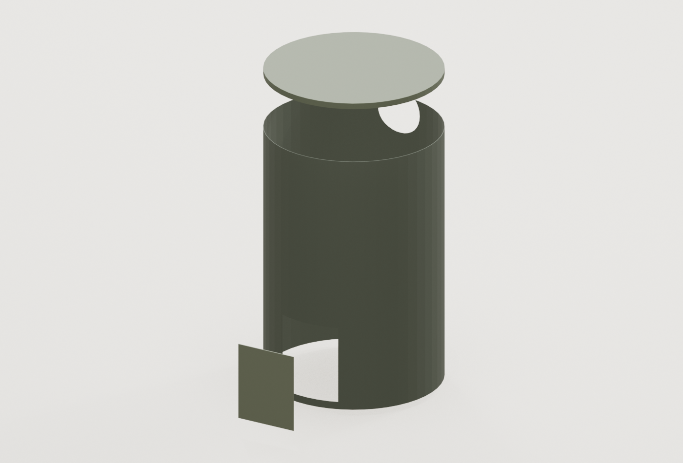
Resolve the drum’s previous contents/coatings, cut edges, pipe overlap, elbow, thermal expansion, condensate and cleaning access.
The model uses an unresolved vertical upstand for the elbow. Historical galvanized pipe is not a present material approval.
Review commissioning and cleaning
Assess any current exterior-only coating, keeping the interior uncoated in this study. Inspect removable racks, tray, baffle and the cooled drum/duct.
Fire design, sanitation intervals, smoke performance and food endpoints remain unvalidated.
Tools by operation
measure and mark
Measure dressed section, mark panels and square cuts
cut plywood
Cut six enclosure panels and baffle from sheet stock
cut frame
Crosscut posts, braces, runners and tray supports
rip racks
Rip eight actual-section boards into sixteen rack bars, then cut adapted end seats
drill panel openings
Start and cut the bottom pipe opening and proposed exhaust pattern
prepare drum
Cut and refit the drum door and outlet; source specifies cold chisel and hand hacksaw outside the 36-tool catalogue
assemble wood
Join panels, braces and removable supports with reviewed fasteners and pilots
attach mesh and hooks
Secure hardware cloth and fit eye hooks after pilot-hole and metal-edge review
exterior finish
Coat exterior plywood only, following source placement; coating chemistry remains unapproved
Before you build
Drum history, coatings, duct joints, condensate drainage and fire separation need review. Historical galvanized pipe and plywood are not present material approvals. Rack loads, cleanability and food processes remain unvalidated.
- Drum history, coatings, duct joints, condensate drainage and fire separation need review. Historical galvanized pipe and plywood are not present material approvals. Rack loads, cleanability and food processes remain unvalidated.
- Round drum and hollow duct follow the model. The elbow is the model’s vertical upstand: its bend radius and joints are unresolved. The drum access and outlet openings are cut through its wall; disassembly moves the access panel clear. Drum hardware, curved cutout reuse and rack end seats still need detail review. Hardware cloth is a translucent envelope.
- Default 1,216 mm panels are a kerf-aware adaptation of the article’s nominal 4 ft square plywood panels.
- Actual 38 mm section and split rack thickness are proposed measurements; verify purchased stock.
- Drum size, grade drop, duct rise, supports, vent count, door gap and hardware placement require site and physical review.
What the 3D model leaves out
Round drum and hollow duct follow the model. The elbow is the model’s vertical upstand: its bend radius and joints are unresolved. The drum access and outlet openings are cut through its wall; disassembly moves the access panel clear. Drum hardware, curved cutout reuse and rack end seats still need detail review. Hardware cloth is a translucent envelope.
Taking the model apart separates parts for inspection; it is not an assembly order.
Dimension evidence and geometric checks
Waters and Bond, Commercial Fisheries Review 22(8), 1960, pp. 8–12- id
- positive-dimensions
- ok
- Yes
- id
- rack-contacts
- ok
- Yes
- id
- duct-rise
- ok
- Yes
- detail
- Proposed lower-grade placement; airflow and condensate untested
- id
- baffle-leg-contact
- ok
- Yes
- id
- tray-support-bearing
- ok
- Yes
- areas
- 1,451.61 mm², 1,451.61 mm², 1,451.61 mm², 1,451.61 mm²
- detail
- Positive geometric corner contact; load strength untested
- id
- panel-butt-joints
- ok
- Yes
- id
- door-no-shell-penetration
- ok
- Yes
- id
- underfloor-duct-clearance
- ok
- Yes
- detail
- Geometric clearance only; no fire clearance
- id
- external-post-bearing
- ok
- Yes
- area Each
- 1,451.61 mm²
- detail
- Full horizontal geometric sole; support material, footing, soil and connection unqualified
- id
- stock-fit
- ok
- Yes
- id
- source-board-count
- ok
- Yes
- detail
- 30 whole-section members plus 8 source boards split into 16 rack bars versus 38 nominal pieces listed; stock cutting optimization differs
Reference renders
Fixed views of the original proposal. They do not change with your dimensions.