Solar food dryer
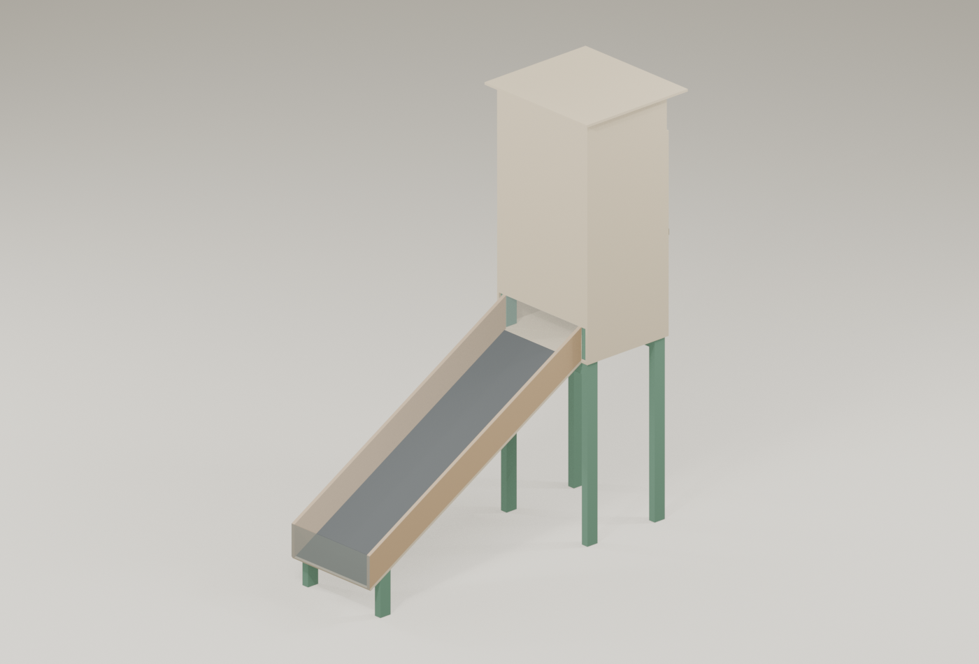
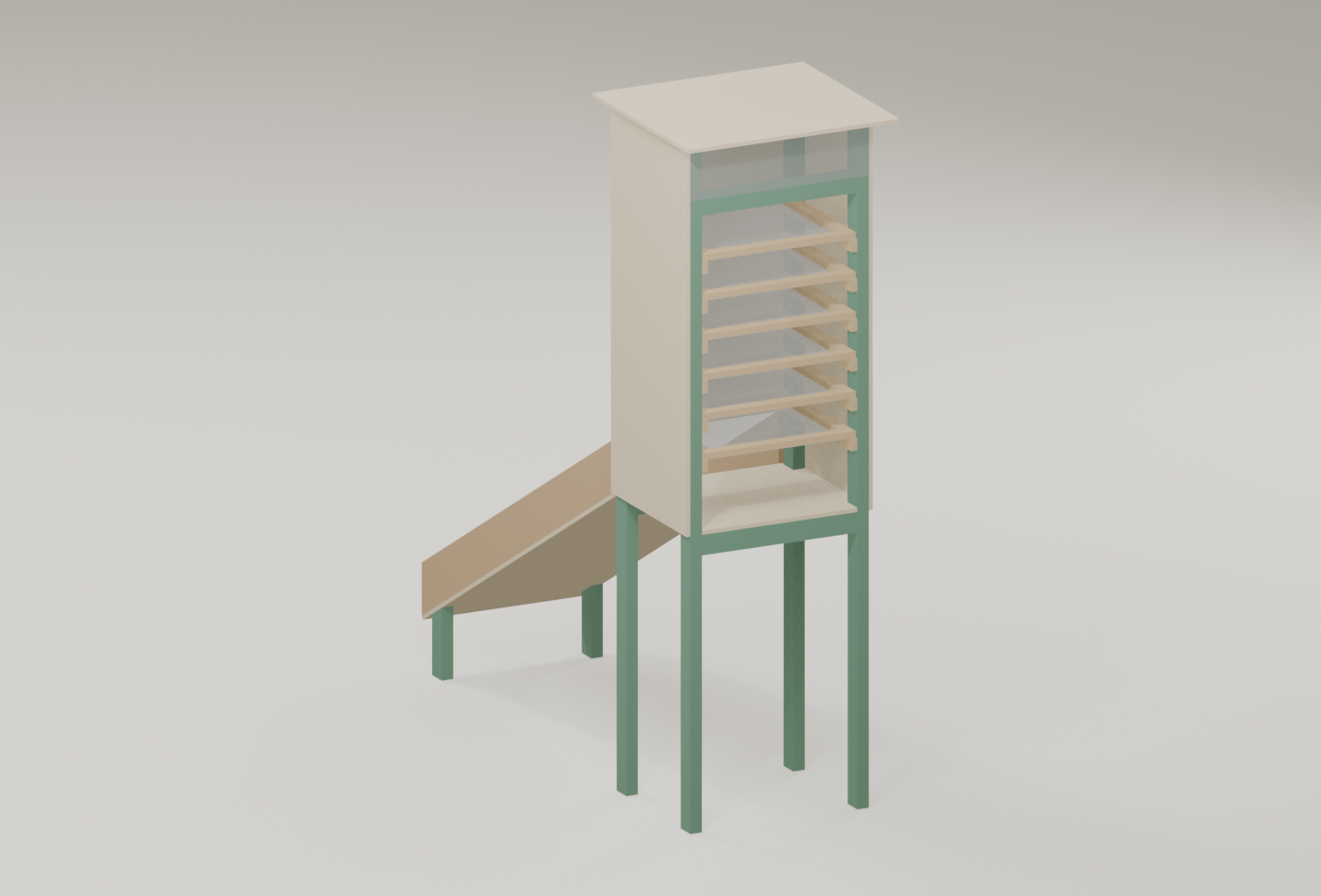
An unpowered timber dryer: a sloped, glazed collector warms air that rises through screened trays in a cabinet and leaves through a screened vent.
Default dimensions are shown below. Enable JavaScript to edit dimensions and inspect the 3D model.
Dimensions
- collector Length
- 1,500 mm
- collector Width
- 520 mm
- collector Tilt Deg
- 30
- width
- 600 mm
- depth
- 500 mm
- height
- 1,200 mm
- tray Count
- 6
- tray Spacing
- 120 mm
- frame Section
- 38 mm, 63 mm
- board Section
- 19 mm, 140 mm
- batten Section
- 19 mm, 38 mm
- sheet Thickness
- 12 mm
- glazing Thickness
- 4 mm
- board Length
- 2,400 mm
- sheet
- 1,220 mm, 2,440 mm
- glazing Sheet
- 1,220 mm, 2,440 mm
- mesh Roll Width
- 1,000 mm
- kerf
- 3 mm
Shopping list
Quantities follow the dimensions above and have not been checked against a built example.
| Quantity | Item | Note |
|---|---|---|
| Timber | ||
| 8 2400 mm lengths | planed softwood batten19 mm × 38 mm section36 cuts · 2,724 mm offcut in total | First-fit estimate with the entered saw kerf. Check grain and defects before cutting. |
| 5 2400 mm lengths | sawn softwood38 mm × 63 mm section9 cuts · 1,685 mm offcut in total | |
| 2 2400 mm lengths | softwood board19 mm × 140 mm section2 cuts · 1,632 mm offcut in total | |
| Sheet | ||
| 2 sheets | 12 mm exterior plywood | 1220 × 2440 mm sheets for the cabinet, door, roof and collector base. Panels are placed one at a time with the entered kerf, not a full nesting plan. |
| 1 sheet | 4 mm clear glazing sheet (twin-wall polycarbonate, acrylic or glass) | One 1220 × 2440 mm sheet; cut 1500 × 520 mm from it. Run twin-wall flutes down the slope. |
| 1 piece | metal sheet for the absorber | At least 1480 × 482 mm of thin aluminium or steel, painted matt black. |
| Mesh and screen | ||
| 1.5 m | food-safe stainless steel mesh | Off a 1000 mm wide roll for 6 trays of 494 × 470 mm. |
| 0.4 m | insect mesh | Off a 1000 mm wide roll for the intake and outlet screens. |
| Fixings and hardware | ||
| 2 hinges | butt hinges | Exterior grade, to suit the door. |
| 3.3 m | door seal strip | Felt or foam weatherstrip round the door. |
| 216 screws | exterior wood screws | Countersunk, about 45 mm long, about 150 mm apart. Drill pilot holes. |
| 12 screws | glazing screws with sealing washers | About 300 mm apart along both collector sides. Drill the glazing oversize so it can move. |
| 1 latch | latch, turn-button or hasp | Holds the back door shut against the door seal. |
| 367 staples | staples | Stainless, about 40 mm apart, for the tray mesh and the screens. |
| Sealants and coatings | ||
| finish, amount not specified | exterior finish for the outside faces | Keep the inside of the cabinet and the trays unfinished. |
| adhesive, amount not specified | exterior wood adhesive | For the frame and panel joints. |
| paint, amount not specified | matt black paint for the absorber | Heat-resistant, for metal. |
| sealant, amount not specified | silicone sealant | For the glazing edges and the collector-to-cabinet joint. |
Cutting plan
Stock allocation uses the model’s kerf rule and the default stock lengths. No piece is spliced to fit.
frame 1frame
2,400 mm- 2,086 mm
- 221 mm
Offcut 87 mm
frame 2frame
2,400 mm- 2,086 mm
- 221 mm
Offcut 87 mm
frame 3frame
2,400 mm- 2,086 mm
Offcut 311 mm
frame 4frame
2,400 mm- 2,086 mm
Offcut 311 mm
frame 5frame
2,400 mm- 500 mm
- 500 mm
- 500 mm
Offcut 891 mm
board 1board
2,400 mm- 1,581 mm
Offcut 816 mm
board 2board
2,400 mm- 1,581 mm
Offcut 816 mm
batten 1batten
2,400 mm- 476 mm
- 476 mm
- 476 mm
- 476 mm
- 476 mm
Offcut 5 mm
batten 2batten
2,400 mm- 476 mm
- 476 mm
- 476 mm
- 476 mm
- 476 mm
Offcut 5 mm
batten 3batten
2,400 mm- 476 mm
- 476 mm
- 470 mm
- 470 mm
- 470 mm
Offcut 23 mm
batten 4batten
2,400 mm- 470 mm
- 470 mm
- 470 mm
- 470 mm
- 470 mm
Offcut 35 mm
batten 5batten
2,400 mm- 470 mm
- 470 mm
- 470 mm
- 470 mm
- 418 mm
Offcut 87 mm
batten 6batten
2,400 mm- 418 mm
- 418 mm
- 418 mm
- 418 mm
- 418 mm
Offcut 295 mm
batten 7batten
2,400 mm- 418 mm
- 418 mm
- 418 mm
- 418 mm
- 418 mm
Offcut 295 mm
batten 8batten
2,400 mm- 418 mm
Offcut 1,979 mm
plywood 1
1,220 mm × 2,440 mm- 520 mm × 1,493 mm
- 600 mm × 1,008 mm
- 1,014 mm × 576 mm· turned
Placed one piece at a time with the entered kerf; not a nesting plan.
plywood 2
1,220 mm × 2,440 mm- 488 mm × 1,188 mm
- 488 mm × 1,188 mm
- 620 mm × 680 mm
- 488 mm × 576 mm
Placed one piece at a time with the entered kerf; not a nesting plan.
Cut list
| Part | Stock | Cut | Joint and angles |
|---|---|---|---|
| plywood | 1,188 mm × 488 mm | Cut and joint details require physical verification. Saw angle from square 0° | |
| plywood | 1,188 mm × 488 mm | Cut and joint details require physical verification. Saw angle from square 0° | |
| plywood | 1,014 mm × 576 mm | Cut and joint details require physical verification. Saw angle from square 0° | |
| plywood | 576 mm × 488 mm | Cut and joint details require physical verification. Saw angle from square 0° | |
| plywood | 680 mm × 620 mm | Cut and joint details require physical verification. Saw angle from square 0° | |
| plywood | 1,008 mm × 600 mm | Cut and joint details require physical verification. Saw angle from square 0° | |
| frame | 2,086 mm × 63 mm | Cut and joint details require physical verification. Saw angle from square 0° | |
| frame | 2,086 mm × 63 mm | Cut and joint details require physical verification. Saw angle from square 0° | |
| frame | 2,086 mm × 63 mm | Cut and joint details require physical verification. Saw angle from square 0° | |
| frame | 2,086 mm × 63 mm | Cut and joint details require physical verification. Saw angle from square 0° | |
| frame | 500 mm × 63 mm | Cut and joint details require physical verification. Saw angle from square 0° | |
| frame | 500 mm × 63 mm | Cut and joint details require physical verification. Saw angle from square 0° | |
| frame | 500 mm × 63 mm | Cut and joint details require physical verification. Saw angle from square 0° | |
| batten | 476 mm × 38 mm | Cut and joint details require physical verification. Saw angle from square 0° | |
| batten | 476 mm × 38 mm | Cut and joint details require physical verification. Saw angle from square 0° | |
| batten | 470 mm × 38 mm | Cut and joint details require physical verification. Saw angle from square 0° | |
| batten | 470 mm × 38 mm | Cut and joint details require physical verification. Saw angle from square 0° | |
| batten | 418 mm × 38 mm | Cut and joint details require physical verification. Saw angle from square 0° | |
| batten | 418 mm × 38 mm | Cut and joint details require physical verification. Saw angle from square 0° | |
| batten | 476 mm × 38 mm | Cut and joint details require physical verification. Saw angle from square 0° | |
| batten | 476 mm × 38 mm | Cut and joint details require physical verification. Saw angle from square 0° | |
| batten | 470 mm × 38 mm | Cut and joint details require physical verification. Saw angle from square 0° | |
| batten | 470 mm × 38 mm | Cut and joint details require physical verification. Saw angle from square 0° | |
| batten | 418 mm × 38 mm | Cut and joint details require physical verification. Saw angle from square 0° | |
| batten | 418 mm × 38 mm | Cut and joint details require physical verification. Saw angle from square 0° | |
| batten | 476 mm × 38 mm | Cut and joint details require physical verification. Saw angle from square 0° | |
| batten | 476 mm × 38 mm | Cut and joint details require physical verification. Saw angle from square 0° | |
| batten | 470 mm × 38 mm | Cut and joint details require physical verification. Saw angle from square 0° | |
| batten | 470 mm × 38 mm | Cut and joint details require physical verification. Saw angle from square 0° | |
| batten | 418 mm × 38 mm | Cut and joint details require physical verification. Saw angle from square 0° | |
| batten | 418 mm × 38 mm | Cut and joint details require physical verification. Saw angle from square 0° | |
| batten | 476 mm × 38 mm | Cut and joint details require physical verification. Saw angle from square 0° | |
| batten | 476 mm × 38 mm | Cut and joint details require physical verification. Saw angle from square 0° | |
| batten | 470 mm × 38 mm | Cut and joint details require physical verification. Saw angle from square 0° | |
| batten | 470 mm × 38 mm | Cut and joint details require physical verification. Saw angle from square 0° | |
| batten | 418 mm × 38 mm | Cut and joint details require physical verification. Saw angle from square 0° | |
| batten | 418 mm × 38 mm | Cut and joint details require physical verification. Saw angle from square 0° | |
| batten | 476 mm × 38 mm | Cut and joint details require physical verification. Saw angle from square 0° | |
| batten | 476 mm × 38 mm | Cut and joint details require physical verification. Saw angle from square 0° | |
| batten | 470 mm × 38 mm | Cut and joint details require physical verification. Saw angle from square 0° | |
| batten | 470 mm × 38 mm | Cut and joint details require physical verification. Saw angle from square 0° | |
| batten | 418 mm × 38 mm | Cut and joint details require physical verification. Saw angle from square 0° | |
| batten | 418 mm × 38 mm | Cut and joint details require physical verification. Saw angle from square 0° | |
| batten | 476 mm × 38 mm | Cut and joint details require physical verification. Saw angle from square 0° | |
| batten | 476 mm × 38 mm | Cut and joint details require physical verification. Saw angle from square 0° | |
| batten | 470 mm × 38 mm | Cut and joint details require physical verification. Saw angle from square 0° | |
| batten | 470 mm × 38 mm | Cut and joint details require physical verification. Saw angle from square 0° | |
| batten | 418 mm × 38 mm | Cut and joint details require physical verification. Saw angle from square 0° | |
| batten | 418 mm × 38 mm | Cut and joint details require physical verification. Saw angle from square 0° | |
| board | 1,581 mm × 140 mm | Both ends cut plumb, 30° off square and parallel; 1,500 mm along each edge. Saw angle from square 30° | |
| board | 1,581 mm × 140 mm | Both ends cut plumb, 30° off square and parallel; 1,500 mm along each edge. Saw angle from square 30° | |
| plywood | 1,493 mm × 520 mm | Square ends. Saw angle from square 0° | |
| frame | 221 mm × 63 mm | Top bevelled to the tilt; 221 mm on the long edge. Saw angle from square 30° | |
| frame | 221 mm × 63 mm | Top bevelled to the tilt; 221 mm on the long edge. Saw angle from square 30° | |
| tray mesh | 494 mm × 470 mm | Cut and joint details require physical verification. Saw angle from square 0° | |
| tray mesh | 494 mm × 470 mm | Cut and joint details require physical verification. Saw angle from square 0° | |
| tray mesh | 494 mm × 470 mm | Cut and joint details require physical verification. Saw angle from square 0° | |
| tray mesh | 494 mm × 470 mm | Cut and joint details require physical verification. Saw angle from square 0° | |
| tray mesh | 494 mm × 470 mm | Cut and joint details require physical verification. Saw angle from square 0° | |
| tray mesh | 494 mm × 470 mm | Cut and joint details require physical verification. Saw angle from square 0° | |
| insect mesh | 576 mm × 177 mm | Cut and joint details require physical verification. Saw angle from square 0° | |
| insect mesh | 520 mm × 162 mm | Cut and joint details require physical verification. Saw angle from square 0° |
Openings and fitted details
- id
- inlet.slot
- type
- rectangle
- width
- 500 mm
- height
- 162 mm
- centre
- 300 mm, 1,305 mm, 991 mm
- target Id
- panel.front
- status
- warm air from the collector enters here, under the lowest tray
- id
- outlet.slot
- type
- rectangle
- width
- 500 mm
- height
- 162 mm
- centre
- 300 mm, 1,787 mm, 2,006 mm
- target Id
- door
- status
- proposal: the same size as the inlet, screened, sheltered by the roof overhang
- id
- collector.intake
- type
- rectangle
- width
- 482 mm
- height
- 162 mm
- centre
- 300 mm, 0 mm, 241 mm
- target Id
- screen.intake
- status
- open low end of the collector, screened
Parts
| Part | Material | Size | Basis |
|---|---|---|---|
| plywood | 12 mm × 488 mm × 1,188 mm | proposal | |
| plywood | 12 mm × 488 mm × 1,188 mm | proposal | |
| plywood | 576 mm × 12 mm × 1,014 mm | proposal | |
| plywood | 576 mm × 488 mm × 12 mm | proposal | |
| plywood | 680 mm × 620 mm × 12 mm | proposal | |
| plywood | 600 mm × 12 mm × 1,008 mm | proposal | |
| sawn softwood | 38 mm × 63 mm × 2,086 mm | proposal | |
| sawn softwood | 38 mm × 63 mm × 2,086 mm | proposal | |
| sawn softwood | 38 mm × 63 mm × 2,086 mm | proposal | |
| sawn softwood | 38 mm × 63 mm × 2,086 mm | proposal | |
| sawn softwood | 500 mm × 38 mm × 63 mm | proposal | |
| sawn softwood | 500 mm × 38 mm × 63 mm | proposal | |
| sawn softwood | 500 mm × 38 mm × 63 mm | proposal | |
| planed softwood batten | 19 mm × 476 mm × 38 mm | proposal | |
| planed softwood batten | 19 mm × 476 mm × 38 mm | proposal | |
| food safe stainless steel mesh | 494 mm × 470 mm × 1 mm | proposal | |
| planed softwood batten | 38 mm × 470 mm × 19 mm | proposal | |
| planed softwood batten | 38 mm × 470 mm × 19 mm | proposal | |
| planed softwood batten | 418 mm × 38 mm × 19 mm | proposal | |
| planed softwood batten | 418 mm × 38 mm × 19 mm | proposal | |
| planed softwood batten | 19 mm × 476 mm × 38 mm | proposal | |
| planed softwood batten | 19 mm × 476 mm × 38 mm | proposal | |
| food safe stainless steel mesh | 494 mm × 470 mm × 1 mm | proposal | |
| planed softwood batten | 38 mm × 470 mm × 19 mm | proposal | |
| planed softwood batten | 38 mm × 470 mm × 19 mm | proposal | |
| planed softwood batten | 418 mm × 38 mm × 19 mm | proposal | |
| planed softwood batten | 418 mm × 38 mm × 19 mm | proposal | |
| planed softwood batten | 19 mm × 476 mm × 38 mm | proposal | |
| planed softwood batten | 19 mm × 476 mm × 38 mm | proposal | |
| food safe stainless steel mesh | 494 mm × 470 mm × 1 mm | proposal | |
| planed softwood batten | 38 mm × 470 mm × 19 mm | proposal | |
| planed softwood batten | 38 mm × 470 mm × 19 mm | proposal | |
| planed softwood batten | 418 mm × 38 mm × 19 mm | proposal | |
| planed softwood batten | 418 mm × 38 mm × 19 mm | proposal | |
| planed softwood batten | 19 mm × 476 mm × 38 mm | proposal | |
| planed softwood batten | 19 mm × 476 mm × 38 mm | proposal | |
| food safe stainless steel mesh | 494 mm × 470 mm × 1 mm | proposal | |
| planed softwood batten | 38 mm × 470 mm × 19 mm | proposal | |
| planed softwood batten | 38 mm × 470 mm × 19 mm | proposal | |
| planed softwood batten | 418 mm × 38 mm × 19 mm | proposal | |
| planed softwood batten | 418 mm × 38 mm × 19 mm | proposal | |
| planed softwood batten | 19 mm × 476 mm × 38 mm | proposal | |
| planed softwood batten | 19 mm × 476 mm × 38 mm | proposal | |
| food safe stainless steel mesh | 494 mm × 470 mm × 1 mm | proposal | |
| planed softwood batten | 38 mm × 470 mm × 19 mm | proposal | |
| planed softwood batten | 38 mm × 470 mm × 19 mm | proposal | |
| planed softwood batten | 418 mm × 38 mm × 19 mm | proposal | |
| planed softwood batten | 418 mm × 38 mm × 19 mm | proposal | |
| planed softwood batten | 19 mm × 476 mm × 38 mm | proposal | |
| planed softwood batten | 19 mm × 476 mm × 38 mm | proposal | |
| food safe stainless steel mesh | 494 mm × 470 mm × 1 mm | proposal | |
| planed softwood batten | 38 mm × 470 mm × 19 mm | proposal | |
| planed softwood batten | 38 mm × 470 mm × 19 mm | proposal | |
| planed softwood batten | 418 mm × 38 mm × 19 mm | proposal | |
| planed softwood batten | 418 mm × 38 mm × 19 mm | proposal | |
| insect mesh | 576 mm × 1 mm × 177 mm | proposal | |
| softwood board | 19 mm × 1,299 mm × 912 mm | proposal | |
| softwood board | 19 mm × 1,299 mm × 912 mm | proposal | |
| plywood | 520 mm × 1,299 mm × 757 mm | proposal | |
| black absorber sheet | 482 mm × 1,282 mm × 741 mm | thin metal sheet painted matt black; cut to this size | |
| clear glazing | 520 mm × 1,301 mm × 753 mm | cut from the glazing sheet; twin wall flutes run down the slope | |
| insect mesh | 520 mm × 1 mm × 162 mm | proposal | |
| sawn softwood | 38 mm × 63 mm × 221 mm | proposal | |
| sawn softwood | 38 mm × 63 mm × 221 mm | proposal | |
| hinge | 3 mm × 30 mm × 60 mm | position marker; hinge size not selected | |
| hinge | 3 mm × 30 mm × 60 mm | position marker; hinge size not selected | |
| door latch | 30 mm × 12 mm × 30 mm | position marker; turn button or hasp |
Build steps and tools
Choose the site and the tilt
Pick a spot in full sun for the whole drying day, with the collector facing south in the northern hemisphere and north in the southern. Set the collector tilt near your latitude: Warm Heart Worldwide puts it at roughly the local latitude, and USU Extension at the best solar-panel angle for your latitude and the season you dry in. The model then sets the cabinet floor height and the post length.
Tape measure.
tape measureBuy and measure the materials
Buy the glazing sheet, a thin metal sheet for the absorber, food-safe stainless steel mesh for the trays and insect mesh for the screens. Window screen does not belong on the trays, and the wood inside the cabinet stays untreated. Measure the timber, plywood, glazing and mesh roll and enter their real sizes.
Tape measure and pencil.
tape measuremarking pencilCut the plywood
Mark the sides, front panel, floor, roof, back door and collector base from the cutting plan and cut them square. Notch the floor where the four posts pass through it.
Circular saw with a guide, jigsaw or handsaw, with a square and pencil. A mitre saw cannot cut sheet.
circular sawjigsawhandsawsquaremarking pencilCut the frame and collector sides
Crosscut the four posts, the two floor bearers and the back rail square. Cut the tops of the two collector legs at the tilt angle. Mark both ends of each collector side board plumb, at the angle in the cut list and parallel to each other, so they stand vertical when the collector is set up.
Handsaw or mitre saw with a square; a sliding bevel, which the tool list does not include, carries the angle.
handsawmitre sawsquareBuild the cabinet
Screw the floor bearers between the front posts and between the back posts at the floor height. Lay the floor on them, then fix the sides to the posts, the front panel above the inlet slot, the back rail under the outlet and the roof on top. Glue the frame joints and drill a pilot and countersink for every screw.
Drill/driver with pilot, countersink and driver bits; clamps and a square to hold the corners true.
drill driverdrill bitcountersink bitdriver bitclampsquareFit the runners and make the trays
Screw a pair of runners to the inside faces of the posts at each listed height and check they are level. Screw each tray frame together at the corners, then staple the food-safe mesh tight across its underside. Slide every tray in and out through the back to check it runs freely.
Drill/driver, staple gun and mesh shears; a sander for the cut ends.
drill driverdriver bitstaple gunshearssanderBuild the collector
Screw the base to the underside of the two side boards. Paint the absorber matt black and lay it on the base between the boards. Fix the glazing to the top edges with screws and sealing washers in oversize holes, and seal its edges; twin-wall flutes run down the slope. The low end stays open for air.
Drill/driver with bits, a brush for the paint and a knife to trim sealant.
drill driverdrill bitdriver bitpaint brushutility knifeJoin the collector and anchor the dryer
Stand the cabinet level on its posts. Offer the collector up so its plumb top end meets the cabinet front under the front panel and its channel floor lines up with the cabinet floor. Screw the side boards to the cabinet, seal the joint and stand the low end on its two legs. Anchor the dryer against wind: USU Extension stakes its community dryer down with six metal stakes.
Drill/driver and clamps; two people lift the collector.
drill driverdriver bitclampFit the screens, door and finish
Staple insect mesh across the collector intake and across the outlet under the roof, with no gaps at the edges. Hang the back door with its seal strip and latch. Finish the outside faces only, and cover the flat roof so it sheds rain; USU Extension uses shingles over underlayment.
Staple gun and shears; screwdriver for the hinges; a brush for the finish.
staple gunshearsscrewdriverpaint brushCheck before use
Run the dryer empty on a sunny day. Look for gaps that let insects or rain in, check that the door closes on its seal and that air leaves through the outlet. This model sets no drying temperature or time; take those for each food from a tested food-preservation source.
A temperature and humidity instrument shows what the cabinet does, without setting any target.
hygrometer
Tools by operation
measure and mark
Measure the timber, sheet, glazing and mesh you bought, then mark the parts from the cut list
cut panels
Cut the cabinet panels, door, roof and collector base from plywood
cut frame
Crosscut the posts, rails and bearers square; cut the collector legs with the top bevelled to the tilt
cut collector sides
Cut both ends of each collector side board plumb at the tilt angle, so the ends stand vertical when the collector is set up
assemble cabinet
Glue and screw the bearers between the posts, then fix the floor, sides, front panel and roof with pilot holes
fit runners and door
Screw the tray runners to the inside faces of the posts at the listed heights; hang the back door and fit the latch
make trays
Cut and screw the tray frames, then staple food-safe mesh tight across the underside
build collector
Screw the collector base to the side boards, paint the absorber matt black and lay it in, then fix and seal the glazing
join and site
Set the cabinet in full sun, fix the collector to the cabinet front over the inlet, stand it on its legs and anchor the dryer against wind
fit screens
Staple insect mesh over the collector intake and the outlet under the roof
check before use
Run the dryer empty in sun and check the airflow, door seal and screens, and that no gap lets insects past the mesh
Before you build
An original design after published indirect dryers. Weather sealing, how the glazing is fixed, keeping insects out and the food process are on the builder; the model sets no drying temperature or time. Check the stand against wind, the tray loads and the door seal before use.
- An original design after published indirect dryers. Weather sealing, how the glazing is fixed, keeping insects out and the food process are on the builder; the model sets no drying temperature or time. Check the stand against wind, the tray loads and the door seal before use.
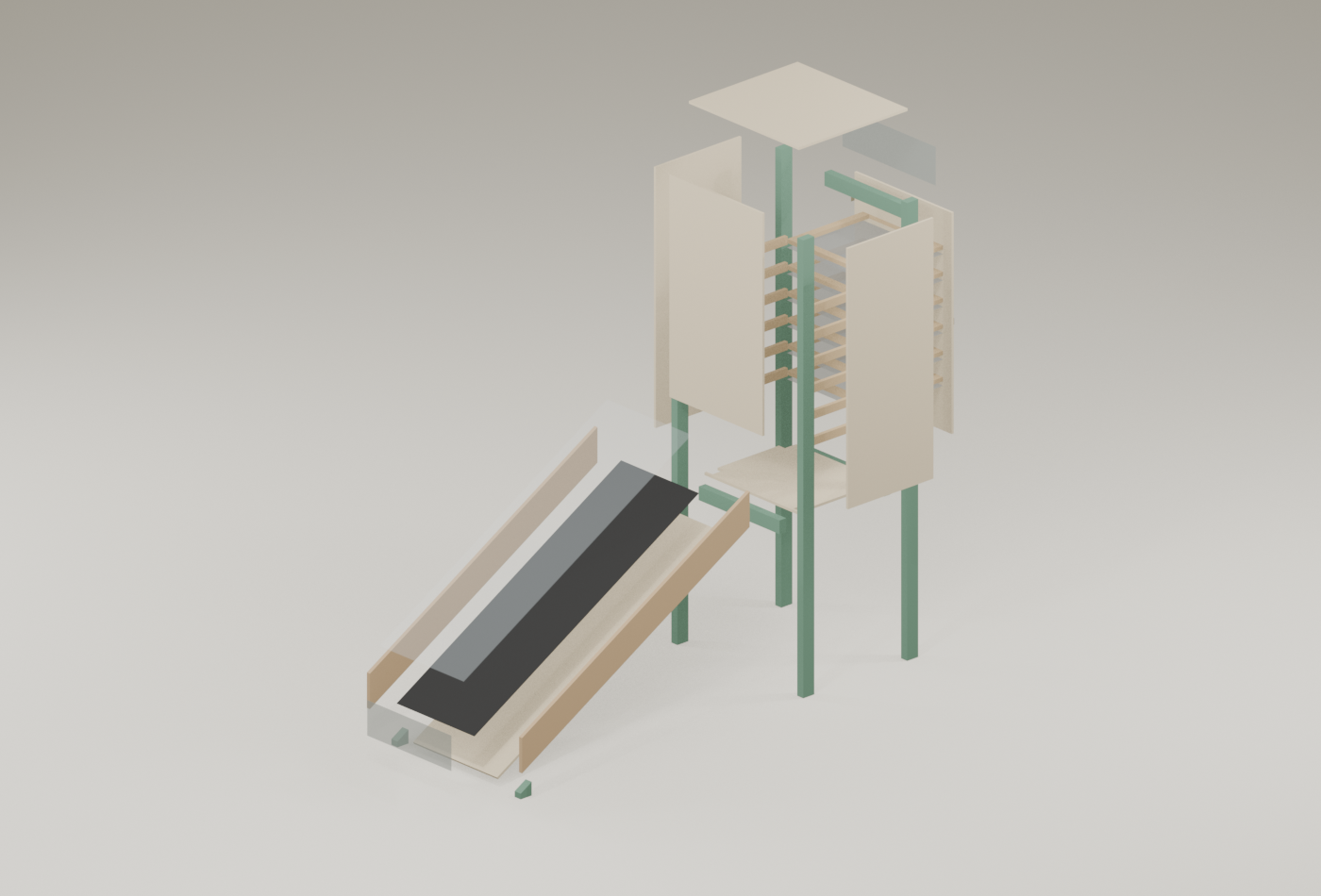
- Cabinet panels, posts, runners, trays and the tilted collector follow the model. The collector parts are drawn from their corners at the entered tilt. Mesh and glazing are translucent sheets; twin-wall flutes, screws, staples and seals are not drawn. Hinges and latch are position markers. The inlet and outlet are open slots, listed under openings.
- Every dimension is a proposal for an original design. Measure your timber, sheet, glazing and mesh and enter the real sizes, and set the tilt for your latitude and season.
What the 3D model leaves out
Cabinet panels, posts, runners, trays and the tilted collector follow the model. The collector parts are drawn from their corners at the entered tilt. Mesh and glazing are translucent sheets; twin-wall flutes, screws, staples and seals are not drawn. Hinges and latch are position markers. The inlet and outlet are open slots, listed under openings.
Taking the model apart separates parts for inspection; it is not an assembly order.
Dimension evidence and geometric checks
- layout
- An indirect dryer: a long, angled, glazed collector box open at its low end feeds solar-heated air into a drying chamber above it, which holds stacked screened trays and has vents under the roof and a back door: Dennis Scanlin, Appalachian State University, in Mother Earth News. Utah State University Extension (Weigel and McCann, 2022) and Warm Heart Worldwide describe the same arrangement.
- collector
- Warm Heart Worldwide suggests a collector 4–6 ft long, 2–3 ft wide and 4–6 in deep, a cabinet the same width, a matt black metal absorber and a glass, acrylic or polycarbonate cover. Scanlin’s collector is 24 in wide with 1 × 6 sides and black metal lath; USU’s has 2 × 6 sides and a plexiglass or twin-wall polycarbonate top.
- tilt
- Tilt the collector to suit the latitude: roughly the local latitude (Warm Heart), the best solar-panel angle for the latitude and season (USU), or Scanlin’s table by latitude. The model takes the angle as entered.
- trays
- Trays 4–6 in apart (Warm Heart). Trays are framed and screened with food-safe stainless mesh, not hardware-store window screen (USU); untreated wood inside the cabinet (Warm Heart).
- screens
- Insect screen over the intake and the vents (Scanlin; USU; Warm Heart).
- outlet
- The outlet slot is made the same size as the inlet. This is a proposal of this model, not a source rule.
- id
- positive-dimensions
- ok
- Yes
- id
- collector-meets-inlet
- ok
- Yes
- detail
- The collector ends at the cabinet front and its channel is no wider than the inlet between the front posts.
- id
- collector-clear-of-ground
- ok
- Yes
- id
- trays-slide-out
- ok
- Yes
- detail
- Every tray clears the runner above it and the top tray passes under the back rail.
- id
- tray-bearing
- ok
- Yes
- bearing
- 16 mm
- id
- glazing-fits-sheet
- ok
- Yes
- id
- stock-fit
- ok
- Yes
Reference renders
Fixed views of the original proposal. They do not change with your dimensions.